Motor One - Finding a Bearing
A Note from 2026
I’m publishing this post for posterity. It was originally written in the summer of 2022. The conclusion I reached at the end isn’t what I’ll be using: I tried it, and it didn’t work. It still stands as part of the research effort, though. See the revised conclusion at the end for where things went next.
The original post continues…
When I initially designed Motor One, I didn’t want to worry about the bearing until I had the key elements in place: fine control of the rotor’s position and its speed. That wasn’t necessarily wrong, but the initial design had something of a timebomb in it. I’ll detail that in a moment; first, the constraints.
The Driving Constraints
While there are no hard constraints on the Motor One pathfinder, the requirements of the future motor still cast something of a shadow. It has to be possible to iterate this design into something which fits inside a model Stargate.
The gate’s symbol ring, which the rotor will be part of, is a tapering surface at the thin diameter of the gate. It also accounts for about half the width between the inner and outer diameters of the gate. At these sizes, it’s easier to scale up than it is down. Two natural constraints fall out of this:
- Minimise the thickness of the rotor. (target=2mm)
- Minimise the width of the rotor. (target=1cm)
Another set of constraints comes from physics: permanent magnets are stronger than electromagnets of the same size (like those used in the stator). The strength of a permanent magnet is a function of the inherent magnetism of the material, and the volume of the magnet. So for the same material, if we halve the volume, we get a quarter of the strength. So, given we still need to optimise the stator to minimise the coil size in the future, it follows that:
- We optimise the permanent magnet last, keeping it as strong (therefore as large) as we can, for as long as we can. (target=8mm dia)
A Problem of Consistency
The problem I’ve been experiencing while developing the motor’s speed controller, which got worse as I slowed the motor down, was inconsistency. By which I mean the RPM varied as it spun, and the motor would often end up in a stalled state.
I can’t say how many index rings (the hall sensor rings) I’ve made in trying to combat this problem. Then I noticed it: the distance between the rotor and the sensor ring was varying quite drastically as it spun, by as much as a centimetre. While I don’t yet know if this is the entire problem, it certainly can’t be helping.
Either way, it’s not meant to do that… It seems prudent to fix the mechanical system before trying to write a precision control system on top of it.
Rotor Mk1 - Skateboard Bearings
The original design, used for all the development so far, has an off-the-shelf 608 skateboard bearing in the centre, with spokes leading away to support the rotor/ring holding the 40 permanent magnets. The construction is 3D printed out of PLA.
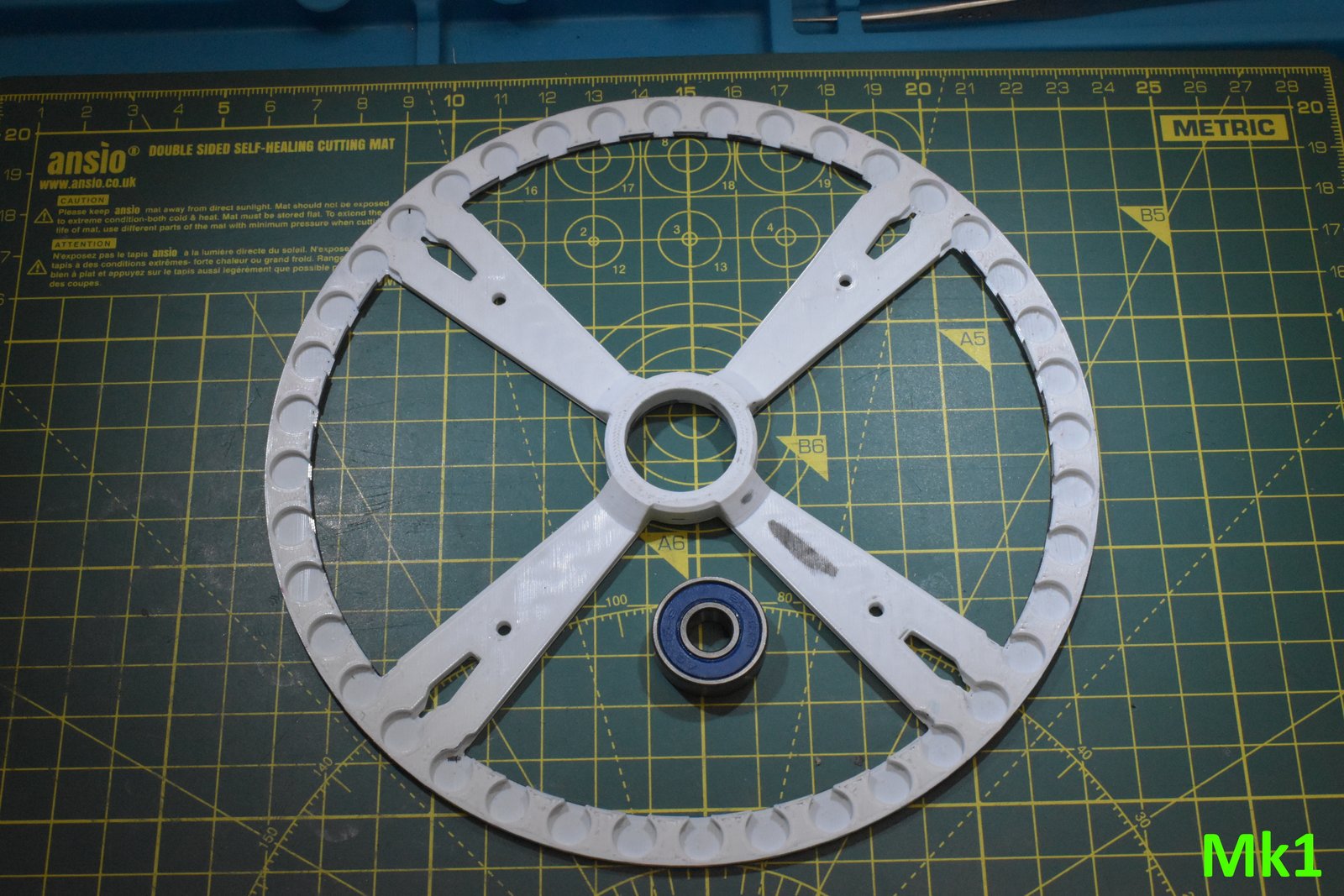
The issue, the timebomb, is that PLA creeps under load, i.e. it deforms over time if a constant force is applied. Turns out 40 N42 neodymium magnets with 1.1kg of pull, held millimetres apart in opposite polarity, is quite the load. The original rotor has substantially deformed. The process of replacing this began my iteration nightmare.
As it turns out, at this thickness with a bunch of holes for the magnets, it seems like I got lucky that this design worked at all. All the subsequent polymer rotors I’ve made, in PLA, PC and PETG (I even CNC milled one out of POM), have imploded once I inserted even half the magnets.
I’m not really sure why this original worked for as long as it did. If I had to speculate, this was one of the last parts I made with my old 3D printer, Bodgebot. I’ve transitioned from Cura to PrusaSlicer, and the new printer meant new profiles, so I just took the default ones as a basis. It’s possible the number of perimeters and top/bottom layers was higher, or maybe I used an infill that did a better job of stiffening the surfaces. It’s worth investigating. There may be a polymer design that does hold up… but that’s not the direction I went in.
Rotor Mk2 - Like Rotor Mk1 but Metal
I bought a fancy new toy recently, a Nomad3 Desktop CNC by Carbide 3D. I can machine aluminium with this. So that’s what I did: I optimised the Mk1 design for CNC. To my surprise, this didn’t work. The separation from the index ring was still variable, perhaps worse than before. It turned out the bearing was inserted slightly off-axis, and since the ring is ~8cm from the centre, any angular offset here produces quite a deflection.
It’s also possible the press fit caused the aluminium part to deform. I’m still getting used to CNC; the bore was undersized, and it took a lot of force to insert.
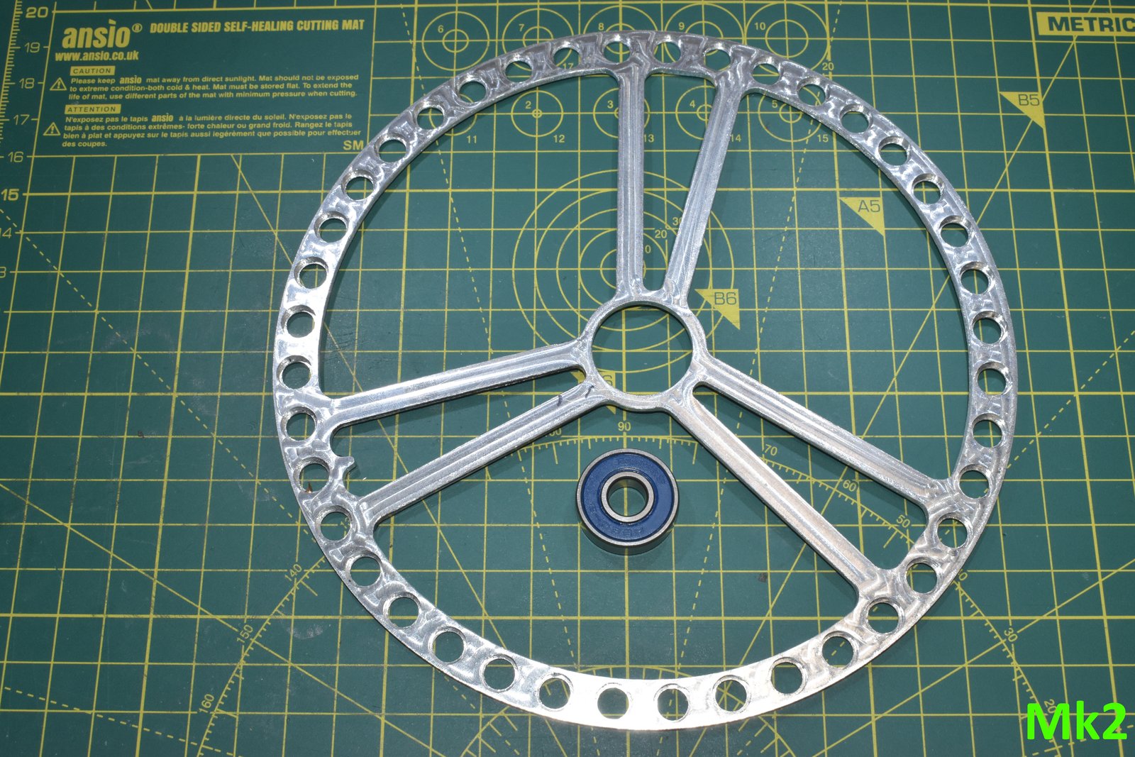
At this point, across Mk1 and Mk2, I’d spent a fair amount of time and effort fixing a part I need to replace anyway. That’s the final issue with this type of rotor: The Stargate does not have spokes. If fixing this design, which was meant to let me focus on the ESC control, is taking this much time, I should probably spend it making something closer to the system I’ll end up using anyway.
Rotors Mk3 & Mk4 - Ball Bearings
The obvious solution is to scale up what I’ve been using so far, a 608 bearing. Let’s look at one.
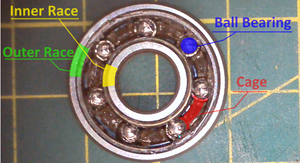
Picture courtesy of a low-resolution USB microscope. I’ve annotated the four primary components.
- Outer Race - larger ring structure with a groove for ball bearings on the inner surface.
- Inner Race - smaller ring structure with a groove for ball bearings on the outer surface.
- Ball Bearings - when torque is applied to the outer or inner races, these roll between them, allowing free rotation.
- Cage - contacts only the ball bearings, not the races, and keeps them a fixed distance apart, preventing them from bunching up.
The races are the interface of rotation, one side will usually be fixed relative to some other structure, while the other can rotate freely. In this bearing, the only thing holding it together is the interference fit of the ball bearings. If the ball bearings disappeared, it would fall apart.
Stator Expansion Interface
A common element in all the following iterations is that they use the Stator Expansion Interface (SEI), meant for the index ring, rather than the centre mount bolt. The interface is four equally spaced M3 holes, starting 45 degrees off-axis, at a radius of 94.456mm. There may have been some arbitrary CAD involved here…
The fact I need to use this interface means I don’t really care about the size of the static race, as long as it’s not obviously impossible to scale down, it can be as large as it needs to be to mate simply with the SEI.
Rotor Mk3
Mk3 implements all the elements of the 608 bearing: the static outer race, the inner race integrated into the rotor, a cage, and fifty 2mm steel ball bearings. The entire assembly is just over 2mm tall.
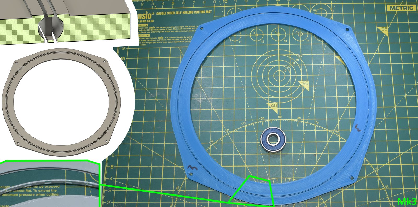
In the top left of the image above there’s a cross section of the CAD assembly. During printing, there’s a pause at the top of the straight before the 45-degree overhangs. At this point the ball bearings are inserted and the print resumed, capturing them in place. In the bottom left there’s an exploded arrangement of the 3D print showing this same area, highlighted in green, which better illustrates the anatomy of the cage.
This design omits the magnet slots; that was merely to speed up printing while iterating. It took several iterations to tune the tolerances for smooth rotation. It does rotate smoothly, but it has a fatal flaw, or three.
- If you place any axial force on the rotor, or flex the assembly, the entire thing just detonates. Motor One is an axial-gap motor. All the force is axial.
- The cage is fragile at only 0.5mm in width.
- The cage is very flexible and has a habit of contacting the inner or outer race as it travels, adding friction.
The key issue here is that I can’t practically use bigger ball bearings: 2mm is already at my height limit, and that’s still too small to make this design work. That comes down to plastic being flexible. In this design the bottom and tops of the races are only a few layers thick, and the overlap between the race and ball-bearings on either side is only 0.5mm. If the assembly flexes by even half a millimetre it breaks apart. This is perhaps made worse by the shape of the race’s groove. Ideally its cross-section would be a semicircle; it’s not. This is a compromise to make it 3D printable.
The cage brings its own issues, for this design to work it has to be printed in place. To give it the best chance of having any strength, I used a 0.25mm nozzle; printing 2 perimeters, with staggered seams. This was to minimise the seam being a weak-spot. At 0.5mm, the clearance on either side is pretty tight at 0.275mm, so I don’t think it would have been practical to make this any thicker. Even then, there’s still a weak spot, the top and bottom bridges between the ball-bearing slots are only a single layer. It’s very prone to breaking here.
The cage also had a habit of slipping off centre slightly, still capturing the ball-bearings, but shifting enough to catch on one of the races, potentially dragging.
An additional, noteworthy but minor, issue is noise. The 50 ball bearings rattle as it turns. This suggests poor manufacturing tolerances, but even fractionally tighter and the system bound up. Grease may have helped here, but I’d probably have to have applied it with a needle.
Despite these flaws, the Mk3 was the best performer until the Mk7.
Rotor Mk4
Mk4 is an evolutionary branch of the Mk3; asking the question, “can I get rid of the cage”?
As discussed above, the main flaw with the Mk3 is it’ll send ball-bearings into low-earth-orbit given half a chance. If we dispose of the cage, we regain about 0.75mm of space, which we can use to further enclose the ball-bearings.
The design and implementation is similar to the Mk3, there are cavities into which the ball bearings are inserted during a mid-print pause, after which the print resumes, entombing them.
On the right side of the image below, there are stacked cross-sections of the same area. The open area on the outer static-race is like that on the Mk3; a constant profile around the circumference. On the inner rotor-race however this area tapers to meet the centre-line. Once a ball-bearing is inserted here, it’s walled and can’t traverse sideways.
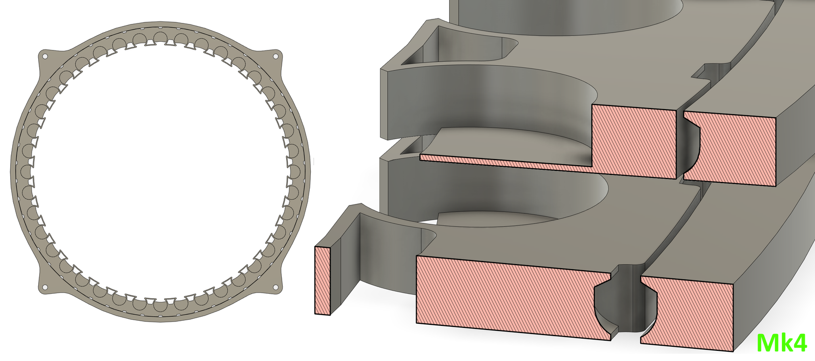
This does keep the ball-bearings at a fixed distance from each other… but in the process introduces severe binding.
I know cageless bearings exist. But none of the designs lock the travel of the ball-bearings to one of the races, and many use alternating direction roller-bearings over ball-bearings. That would appear to be for a very good reason. The cage doesn’t just keep the ball-bearings apart. It critically allows them to move as an independent system at their natural speed.
This is simple physics: for a rotating body, the further out from the centre you measure the faster the apparent speed to cover the same angle about that centre. The ball bearings are not points with zero width; their centre of travel is further out than the rotor race’s outer diameter, which only imparts enough tangential force to move them as if they were. So naturally, if we constrain them to the rotor, we’re going to be dragging them for them to keep up.
This is a terrible bearing. Not only does it not rotate smoothly, it comes apart more easily than its predecessor: it’s bogging steel into plastic, which pushes back with a spring force, causing the assembly to self-destruct.
Rotors Mk5 & Mk6 - Bushing
A bushing is the simplest kind of bearing. It’s two surfaces which rub against each other. They’re generally preferred for low-speed high-torque applications. My application is low-speed low-torque, so even better?
I know this works for a model Stargate, every animated gate I’ve seen has used this principle. The one I made in secondary school used this principle. This should have been at the top of my list of things to try. My main grievance with bushings is that the crunchy sound of plastic rubbing against plastic just bothers me.
I reasoned that I could leverage CNC here to make smoother parts from fancier materials than 3D printing allows, hoping to come up with a design which produced a more tolerable sound in operation.
I would say this section is included for completeness. Neither Mk5 nor Mk6 produced anything usable. Both were beset with machining problems due to my inexperience, though at a minimum they taught me some lessons.
Rotor Mk5
Enter Mk5. It’s machined entirely from acetal (POM, aka Delrin), and has three parts; the rotor, the static ring, and the static retaining ring. The lower left of the image below is a cross sectional view.
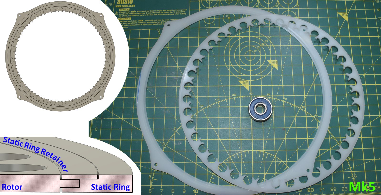
Once the rotor is inserted, the static-ring-retainer is glued to the static ring, and the rotor is free to turn inside. At this point you may be noticing a discrepancy between the CAD on the left, and the object on the right.
The bottom of the magnet slot was bored straight through. Other problems: the fit between the rotor and static ways is too tight. The ‘stick out’ on the outer diameter of the rotor is meant to have equal spacing above and below, and be 1mm thick; it turned out 0.75mm thick, i.e. one cut is much deeper than the other. It’s out of spec. Precision machining is hard and requires skill and experience I don’t yet possess; it’s all new to me, and I’m still learning.
I didn’t have enough POM left for another attempt, so that same day I ended up designing the Mk6 instead. The Mk5 still had a lesson to offer, though.
I mentioned in the Mk1 section how I got lucky; this was where I realised it. A design feature of the Mk5 carried forward from the Mk4, is the branch like structure at the edge of the open magnet slots: a compliant mechanism for inserting the magnets. The mechanism works, the magnets are easy to insert, up to a point.
The insertion order for the magnets is all-even polarity, followed by all odd. With all evens inserted, once about a quarter of the way through the odds, the rotor buckled into a cone shape. The earlier 3D printed versions had simply failed catastrophically; this, for the first time, demonstrated quite visually the interaction between these very strong magnets. Which is obvious in hindsight.
Rotor Mk6
Mk6’s design fell out of a realisation I had when I ran out of material for the Mk5: if the static element was on the inside, I’d have used less material…
On the Stargate, there is a small section under the ring. Below is a reference image of the Atlantis gate from the Propworx auction. The green bracket highlights the ring area. (This gate was actually a repurposed SG-1 ‘hero gate’, i.e. one of those used for on-location filming around Vancouver, so all the proportions are the same.)
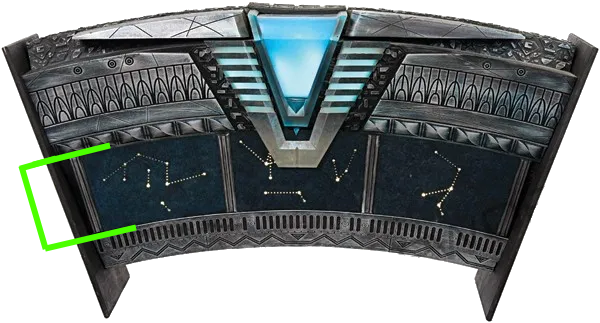
At my scale, this area under the ring would be thin, but a bushing might fit. To use this kind of bearing on Motor One, I needed to create an adaptor for the SEI, which is the strange circular tower in the image below.
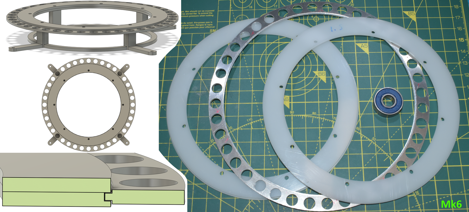
In the bottom left there is the usual cross sectional view. The design is similar to Mk5, with three components, static ring (bottom), static-ring-retainer (top) and the rotor (right).
The static elements are both 2mm thick, made of POM and this time bolt together. I did this for simplicity’s sake. Had I iterated on this design, I’d likely have changed the square ‘stick out’ into a V shape, with the corresponding groove split across two 1mm plates. Either way, these two parts did turn out in-spec.
The rotor however did not.
The rotor is made of aluminium, is 2mm thick, and has ways machined on both sides of the inner circumference, While the depth is right this time, one of them wasn’t concentric, so it didn’t seat correctly in the static element. The part was scrap.
A CNC Aside
Double-sided parts present a difficult problem: when you flip the part you introduce positional and rotational error. One way to mitigate this is ‘indexing’: alignment holes that repeatably fix the part in exactly the same location on your work platform. Alternatively, you build a jig that aligns the part in much the same way.
In my case, I machined my stock to a known square size, then bored indexing holes mirroring the ones in the work platform. I used the Nomad’s ‘BitZero V2’ corner finding block. I suspect my process for squaring it was naive and introduced the error, perhaps there was a slight burr. Either way, the way on the second side was off-centre by as much as half its intended width.
I need to practise machining, and double-sided machining in particular. The entire work flow is quite different from what I’m used to with 3D printing. I know my printers well enough to know what tolerances I need to bake into my designs, and which design patterns allow for which geometry.
Rotor Mk7 - Rollers
Did I replicate the right thing when I built the Mk3? I was attempting to scale up a 608 skateboard bearing. Perhaps that was misguided. While looking at bearing listings, I came across Lazy Susan type bearings. These are large radius bearings, quite similar in proportion to what I’m attempting. They come in all the same variety you’d expect from bearings, including ball-bearings. But many designs use rollers or wheels.
I had considered rollers previously. The original CAD for the Mk3 was designed to accept rollers instead, but I couldn’t find any that small, and there wasn’t a chance I was hacksawing 50 precision 2mm rods. But what if I don’t need 50?
Thus the Mk7 was born. There’s an elephant in the room with this design; I’ll get to that at the end.
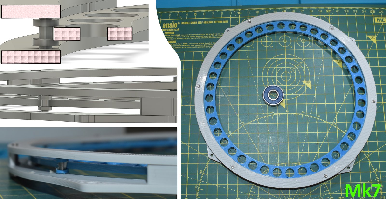
Instead of 50 rollers, this design uses six, equally spaced around the circumference. Each is a 7mm steel rod, with 3D printed washers superglued to them 1mm either side of centre. The rotor is captive to these washers. The assembly is awkward, but not too difficult. The rotor is placed roughly in position, then each roller is inserted around it, and finally the retaining plate is bolted in above it, securing everything in place.
It turns smoothly in both standing and lying-flat orientations. The few contact points make little noise, and it doesn’t explode when loaded axially.
The ultimate proof will be when I replace the 3D printed stand-in with a milled aluminium rotor and try it live. But all indications so far are positive; this seems like a solid candidate design to iterate from.
About that elephant. Mk7 is almost a centimetre tall. That’s far beyond what I consider acceptable, so I’ll need to look into a miniaturisation scheme. But if push comes to shove, you can actually buy tiny flanged bearings; such as the F681, 1mm tall, 3mm OD, 1mm ID. They’re expensive, at £8 a bearing at the time of writing, but definitely an option.
At this point, I’m thinking my miniaturisation strategy would be to bring the rotor height down to 1mm at the outer circumference, and to get access to a lathe to machine a better flanged roller, as the current one is mostly limited by how small and repeatable I can make a part with hand tools. In my head I don’t see why it needs to be any larger than 3mm. It does take more space out of the area I wanted to conserve for electronics, but it at least doesn’t take it around the entire circumference, only at 6 points.
Conclusion
I believe the Mk7 is the best fit for Motor One. I intend to evolve the roller design to be more compact in Motor Two; if I can’t, I’ll re-evaluate my options, which would likely have to be some kind of bushing at that point.
Whatever happens, I think the rotor needs to be metal so it doesn’t deform long term under the internal loading of the magnets.
To summarise:
- Off-the-shelf bearings in the style of Mk1 and Mk2 are out; the gate doesn’t have spokes.
- Captive ball bearings at my target thickness are too fragile, especially with plastic races. Metal races might work, but the machining needed to have a groove on the side is beyond what any tool I own could do.
- Bushings need further investigation. My implementation of them was too poor to pass fair judgement.
- Rollers or wheels seem well suited for this task.
A humbling takeaway is that CNC is hard and I need a lot of practice. The CAD skills I have are somewhat transferable, but even then designing for subtractive manufacture is different. CAM is considerably more complicated than a 3D printer’s slicer. And dealing with the real-world realities of stock sizes, tolerances and alignment is just something that’s going to require practice.
Revised Conclusion (2026)
When I tried running the Mk7, it kept sticking. That may just have been down to the low precision of my rollers, and higher-quality ones might have worked. However, while drawing up the master CAD for Motor Two’s constraints, I realised there simply isn’t space for this kind of arrangement. In reality I have far less room than I thought, especially if I want to fit electronics and the chevron actuators in there too.
I had a stainless steel bearing race set machined through PCBWay’s CNC service, and that bearing ran on the motor. I’d still like to make one myself; since writing this post I’ve acquired a lathe and got a little better at CNC.
Here’s the result: