Motor One
Motor One is the first of three pathfinder projects. It’s purpose is to gain the requisite skills and knowledge to design and construct the motion system for the gate’s ring.
The primary objective of Motor One is to construct a to-project-final-scale BLDC type motor which has the following functions, spin direction control, variable speed control to slow RPMs and precise positional control.
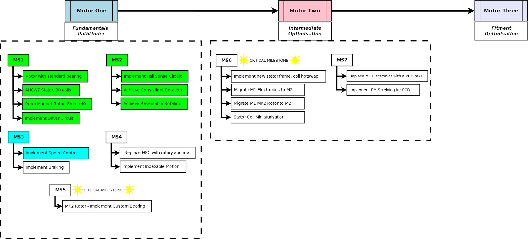
To do this, I have something of a roadmap. There’s no point of planning out too far ahead, but I have a pretty good idea of what I want Motor Two to be, and what I need Motor One to accomplish to get there.
Milestone Zero
Before I did any motor work, I did some preliminary tests with different electromagnet configurations, I never fully concluded these tests as a test accident was actually encouraging enough to just move onto the motor.
The parameters of the test do bear explaining though, as I still use this notation; wire diameter, coil radius, coil height. I selected two wire diameters 0.55mm (Type A), 0.75mm (Type B) and the notation I used for these coils was [A/B]H[height]W[width]. The version I selected for the motor was the largest in the test, the AH6W7 coil. 6 tall, 7 wide. 42 coils.
Milestone One
So… I set to building a motor. Motor fundamentals are out of scope here, though I may do another post detailing them in future.
The two primary components of a motor are the stator and rotor. For my design, the stator is the section with the electromagnets; which are in a non-overlapping, 3-phase configuration, in a 3:4 ratio with the permanent magnets in the rotor. (Fantastic technical reference on those ratios here; https://things-in-motion.blogspot.com/2019/01/selecting-best-pole-and-slot.html).
For development sake, the mark 1 rotor in this design uses an off-the-shelf 608 bearing as its centre bearing, though I know I will have to build a custom bearing for later milestones in Motor One. The entire project actually hinges on the viability of that element. The gate can’t have a bearing in this position.
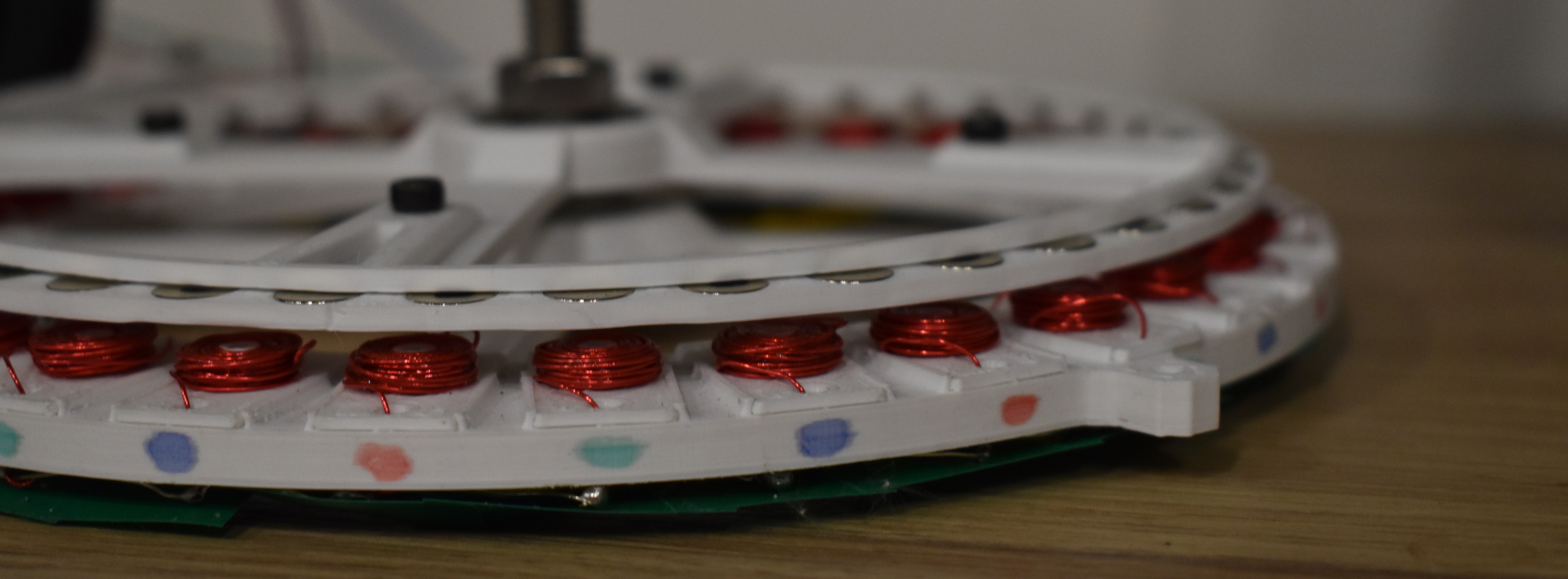
The stator has 30 electromagnet coils, implemented as Coil Plates. They are the above AH6W7 coil design. The plate itself is friction mounted in place. Then each end of each coil was routed through the stator to the underside via two holes at either side of the plate, where they were soldered appropriately.
I am using a typical BLDC Y- configuration. i.e. every coil in a phase is connected in series to every coil in its phase (every 3rd coil is connected together). Then at one end of this chain they are commoned together with the other 2 phases (to form a Y like joint), and the remaining side acts as the input to the phase. That way if you run current through a phase, and sink one of the other inputs to ground you get opposite polarity magnetic fields generated in the 2 now active phases, with the 3rd floating.
For Motor One, the coil design and coil plates won’t change. But I’d like to optimise this design in Motor Two, and would like a more easily swappable plate design.
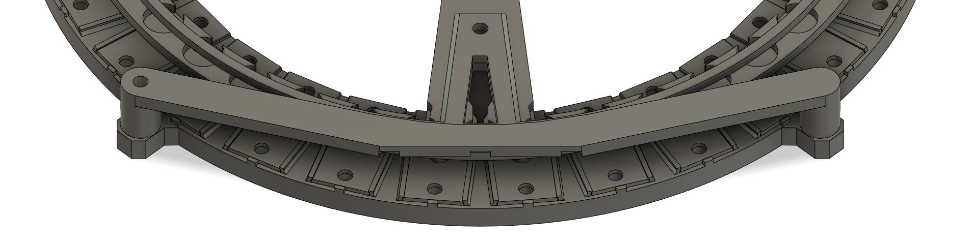
Below are 3D renders of a coil plate without it’s coil on the left. And the whole of Motor One (without actual coils or the 608 on the right).
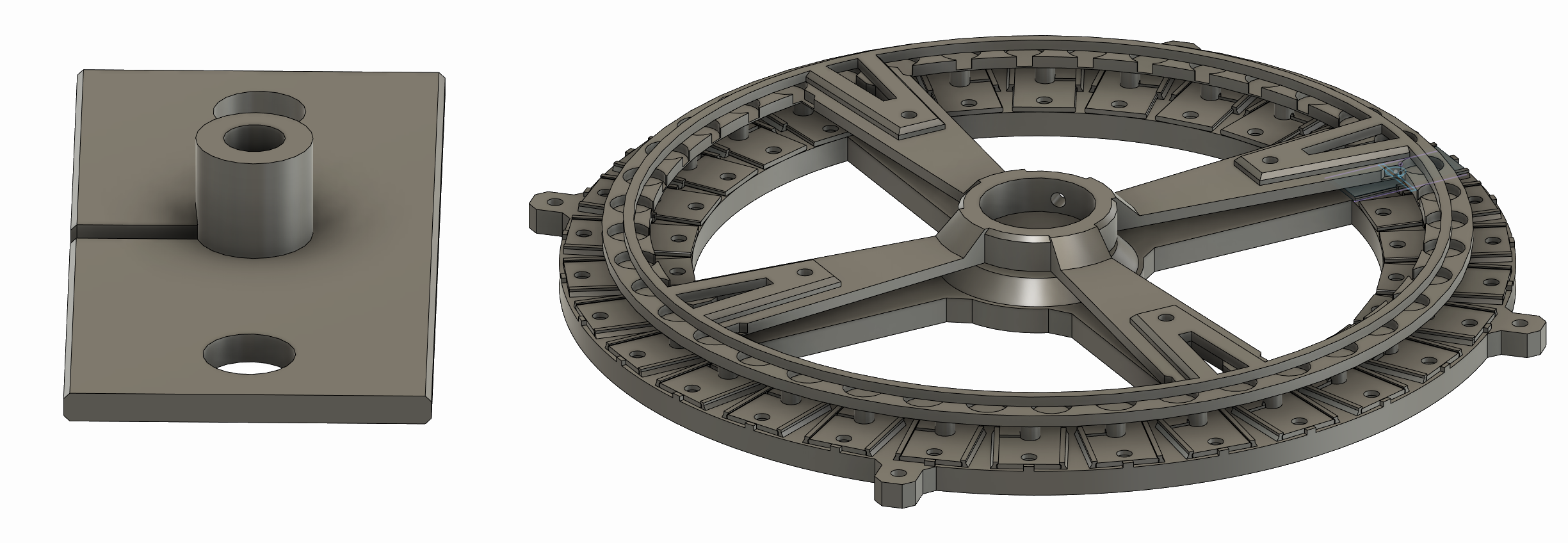
Top Down; Stator Base, Coil Plates, Rotor
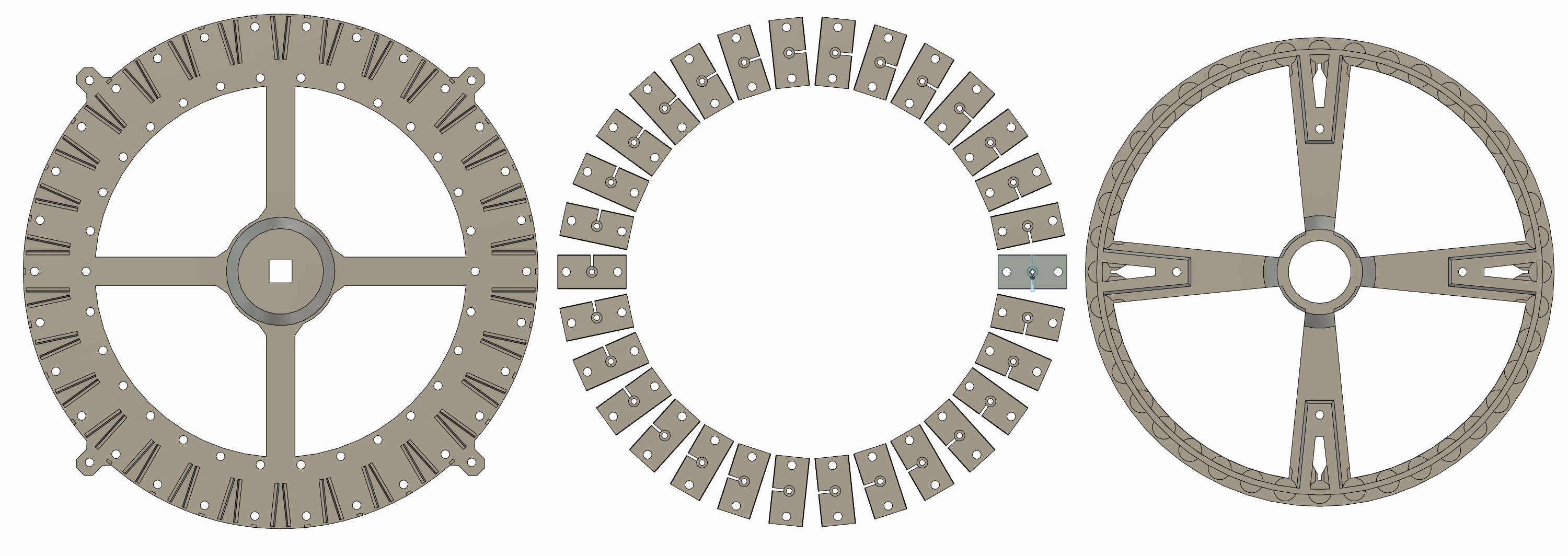
The stator base has 4 expansion holes on it’s outer circumference, the rotor is actually split into two pieces. The main body, and a top retaining plate. I will probably remove the retaining plate in later designs.
Basic Electronics
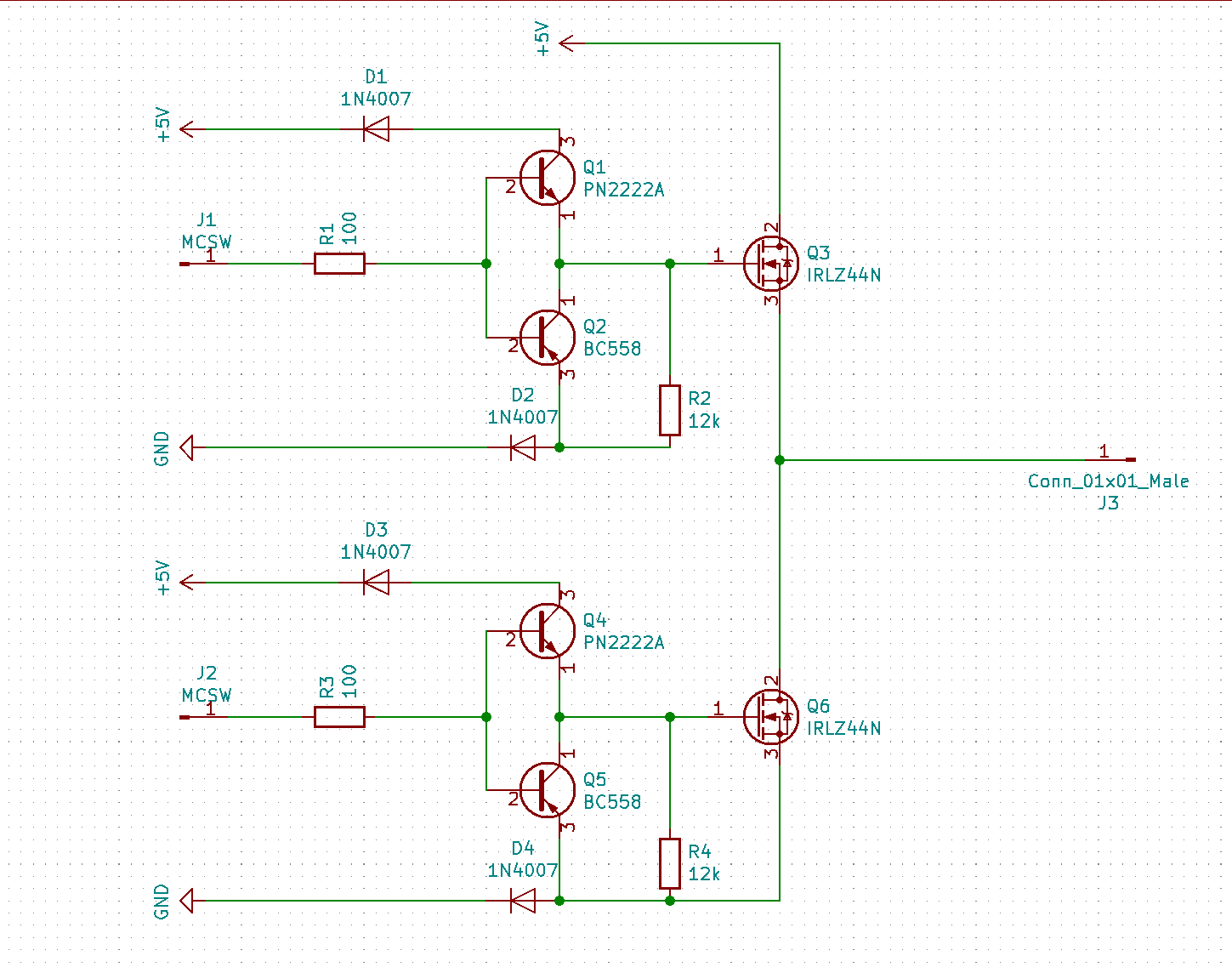
I tried an off-the-shelf sensored ESC, but couldn’t get it to work, so I quickly set to building my own; which I would have to had done eventually anyway. I based my initial design off this project https://simple-circuit.com/pic16f887-sensorless-brushless-motor-control/ - this isn’t a sensored ESC, it uses Back EMF, but the I only needed the MOSFT arrangement, as at the time I only had N-Channel MOSFETs, this was the only design I could find which doesn’t use P-Channel’s for the high side. I also substituted the MOSFET drivers with BJT transistors, as I also didn’t have any of those.
I built 3 of these below, and also added different colour indicator LEDs in parallel with the input and the BJT transistor bases. (e.g. J1 to the connection between Q1 and Q2). Each has two inputs, J1 and J2, which go to the brain of my ESC, a venerable Arduino Nano. 5V applied to J1 makes the output at J3 high, 5V to J2 makes J3 grounded.
Initially I tested without the sensor board, just to see if it would do.. something. Or better yet, to see if I could luck into rotation; and it did kind of work, I did get some kind of rotation maybe 1 in every 5 times. More often than not it just jumped erratically. Initial software - https://github.com/andywm/GateESC/commit/926ff934a161bfabe9f11f8ca7b9dbd7f39e03ea/src/main.cpp
Milestone Two
So, I had achieved erratic motion, time to get fluid motion.
BLDC motors need some kind of feedback to know their position to correctly sequence the motor. A process called commutation, there are two common ways to do this;
BEMF which uses induction in the floating coil, when the induced voltage crosses zero, you sequence the commutation. This looks difficult, so isn’t the route I went for…
Hall Effect Sensors, magnet sensors basically. Placed 120 degrees out of phase with each other in between coils on the stator. They detect the magnets in the rotor when they pass over. 1 or 2 can be active at once, so produce 6 unique combinations indicating when the parament magnet is aligning with stator electromagnets. At which point you switch to the next phase in the sequence misaligning them again, continuing the process of the permanent magnets chasing the rotating field from the stator.
As a quick reference for the commutation table for a 3-phase motor I used this; https://lucidar.me/en/actuators/commutation-for-bldc-motors/
In my current version I built this apparatus and attached it to the stator using the expansion holes. Each sensor lies directly between two coils. Mine are not 120 degrees out of phase, they’re actually between consecutive coils. I think this works for me because I have 30 coils and 40 permanent magnet, so 120 degrees out of phase would be 10 coils distance. So the 10th coil will be the same as the 1st, as will the relative relation with the rotor magnets due to the 3:4 ratio. Which is convenient for me, as it means my apparatus can be ‘compact’.
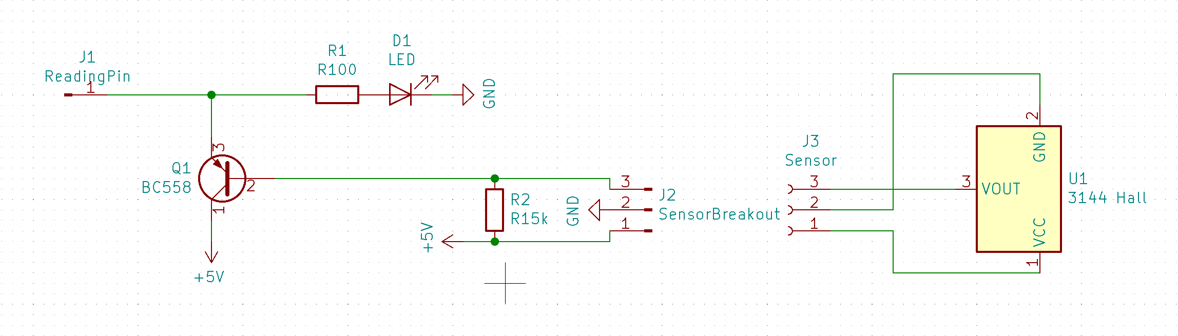
The hall sensors I have are the linear (analogue ) type, rather than digital, so I had to make a bit of circuity to turn the voltage into a binary signal for the Arduino. For my 3144 hall, the stronger the magnetic field, the more Vout drops. So I put a pullup resistor from 5V to the Arduino input/Vout to get a nice high signal when it’s off. Then fed it into a PNP BJT transistor to; (A) give me a nice digital threshold for the signal. (B) invert the signal as active low for this bothers me irrationally. Really I could have done it with a NPN and just read LOW to mean on in software. But I digress.
The hall sense circuit is 3 of these next to each other. It has a nice indicator LED for when the sensor is detecting a magnet for debugging reasons.
I reworked the control software for the ESC, it’s basically a re-write as the first version was just to get it to do.. something. This is the version I will build on. It implements the commutation sequences as well as directional control. And it works reasonably well. https://github.com/andywm/GateESC/blob/3cf6672638acaa5940a3b7476896cb69f5546901/src/main.cpp
Although all-and-all though, this is actually just a stop-gap prove out aspects of the motor; to serve as a development platform. I will need the final ring to have full positional indexing, so will need something much more accurate than these hall sensors. The entire thing will essentially need to be an absolute rotary encoder. Knowing its position to high accuracy at all times. So, when I develop that. Well, I may as well use that for the commutation sequencing too.