<?xml version="1.0" encoding="utf-8"?><feed xmlns="http://www.w3.org/2005/Atom" ><generator uri="https://jekyllrb.com/" version="4.4.1">Jekyll</generator><link href="https://www.andywm.com/feed.xml" rel="self" type="application/atom+xml" /><link href="https://www.andywm.com/" rel="alternate" type="text/html" /><updated>2026-11-05T02:02:04+00:00</updated><id>https://www.andywm.com/feed.xml</id><title type="html">A Palace of Things</title><subtitle>An adventure in making things - realised with 3D printing and terrible engineering principles. There will be sci-fi, and the odd practical thing...</subtitle><entry><title type="html">Project Update 2026</title><link href="https://www.andywm.com/stargate-project/2026/11/05/Project-Update-2026.html" rel="alternate" type="text/html" title="Project Update 2026" /><published>2026-11-05T02:01:38+00:00</published><updated>2026-11-05T02:01:38+00:00</updated><id>https://www.andywm.com/stargate-project/2026/11/05/Project-Update-2026</id><content type="html" xml:base="https://www.andywm.com/stargate-project/2026/11/05/Project-Update-2026.html"><![CDATA[<p>It’s November 202<strong>6</strong>!? The last post was in 2021. This blog was meant as a journaling effort… That’s gone well. <em>This project hasn’t exactly progressed as quickly as I would’ve hoped.</em> Nevertheless, progress has been made!</p>

<p><a href="https://www.youtube.com/watch?v=PFvSWWD3wPI">https://www.youtube.com/watch?v=PFvSWWD3wPI</a></p>

<div class="video"><iframe width="560" height="315" src="https://www.youtube-nocookie.com/embed/PFvSWWD3wPI" title="YouTube video" frameborder="0" allowfullscreen=""></iframe></div>

<p>This post was largely written at the start of 2025; it’s apparently taken me this long to publish it. At the time I was more or less there with Motor One: reasonable speed control, position sensing and a basic dialling program, with a few things still to solve or refine before moving on. That’s still accurate, as I stopped working on this part of the project. I do think it’s in a state where, once I resume work in earnest, finishing it will be a matter of weeks or months, not years.</p>

<p>Let’s look back over the key development areas.</p>

<h2 id="electronic-speed-control-esc">Electronic Speed Control (ESC)</h2>

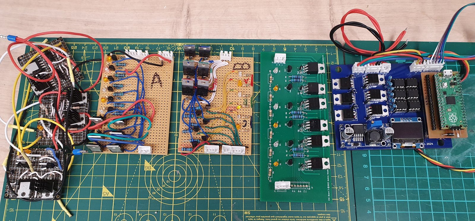
<p>A high-level timeline and summary of the ESC’s development, v0 to v4.3.</p>

<p><img src="/assets/posts/Project-Update-2026/ESCFamilyPortrait.jpg" alt="ESC Family Portrait" /></p>

<p><strong>ESC Versions</strong> - Left to Right</p>

<ul>
  <li>v0 - 2021; the original three-board circuit from the Motor One blog post. Used only n-channel MOSFETs. It kind of worked by chance, really: one of the sub-boards was actually dead, so it was running on two phases, and would randomly stall as a result.</li>
  <li>v1 - 2021; a refined design of the original, moving to a single board, switching to n-channel and p-channel MOSFETs for ground and VDD respectively. v1 unfortunately died when at least one of the MOSFETs cooked itself and went short circuit.</li>
  <li>v2 - 2021; an electrically identical replacement for v1, but better laid out on my test jig. The jig introduced active cooling as a stopgap for the overheating problem. Naming is retroactive, originally these were the A and B boards.</li>
  <li>v3 - 2022; first factory-made ESC PCB (PCBWay). It was intended to be the v2 design transcribed into KiCad, but I made a mistake with the MOSFET routing, requiring bodge wire corrections. I never ended up using this version for that reason, and it’s bloody massive. The point of this design was to have a spare in case I burned out the v2. Populating one of these would be easier than another one-off perfboard job.</li>
  <li>v4 - 2024; switches to the Pi Pico from the Arduino Nano I’d been using up until now, integrates the test harness onto a single board (microcontroller power, power breakouts, screen), and solves the MOSFET thermal issues.</li>
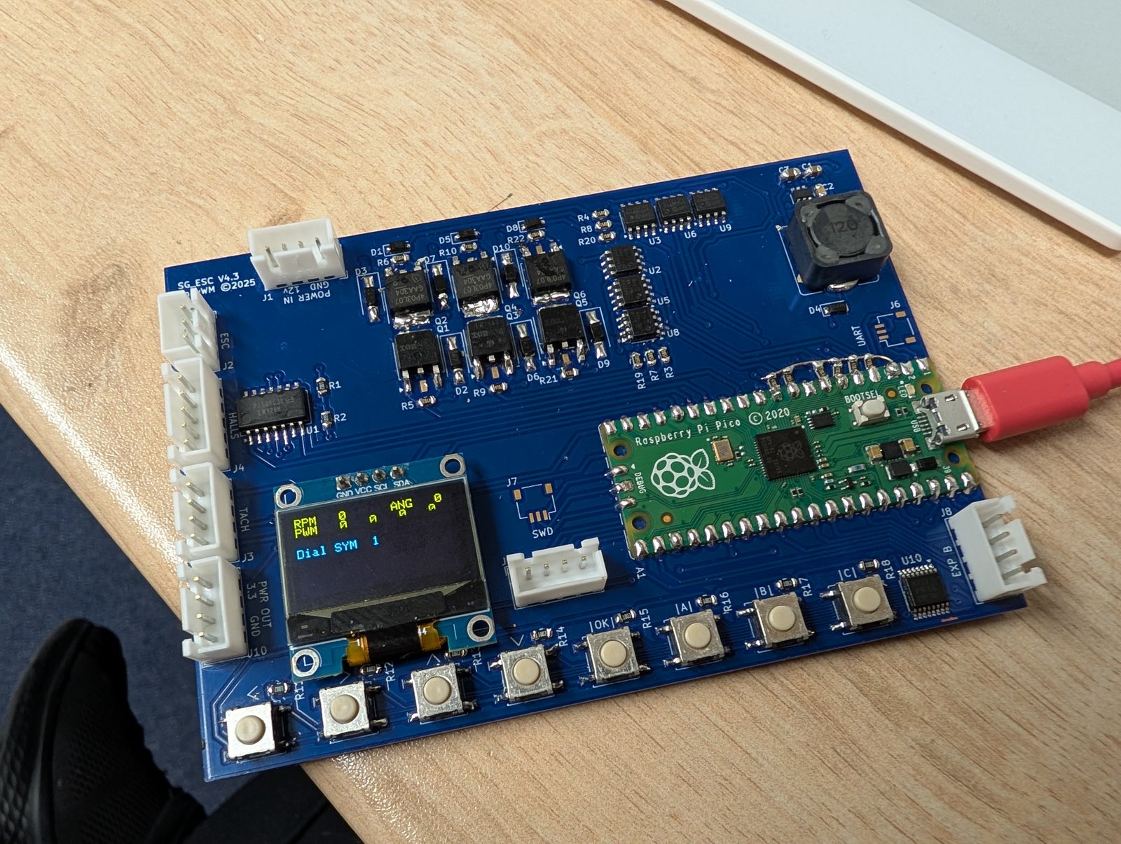
  <li>v4.1 - 2024; revision. Fixes flipped SDA/SCL screen connections, corrects MCU board power with a Schottky diode on VSYS. (never produced)</li>
  <li>v4.2 - 2025; revision. Adds buttons for debug control. (never produced)</li>
  <li>v4.3 - 2026; major component and layout revision. Same electrical schematic, but switched to SMD components and added the buttons for on-device debugging. Adds two breakout headers exposing the remaining pins for the LEDs, sound and chevron lock.</li>
</ul>

<p><img src="/assets/posts/Project-Update-2026/ESCv4.3.jpg" alt="ESC v4.3" /></p>

<p>For most of the development I used the v2. Its main problem was the constant risk of overheating and self-destructing. The v4 solves this. The overheating seems to have been caused by my choice of BJTs for switching the MOSFET gates: they’re too slow for this application, which leaves the MOSFETs spending a lot of time between states, with extreme switching losses. Thus heat, thus damage. The proper solution was to use the proper solution: a gate driver IC. The v4 uses TC4420s.</p>

<p>Videos:</p>

<ul>
  <li>V2 Thermals Test - <a href="https://www.youtube.com/watch?v=9gCmHrg-cko">https://www.youtube.com/watch?v=9gCmHrg-cko</a></li>
</ul>

<div class="video"><iframe width="560" height="315" src="https://www.youtube-nocookie.com/embed/9gCmHrg-cko" title="YouTube video" frameborder="0" allowfullscreen=""></iframe></div>

<ul>
  <li>V4 Spin Test w/o PID, er Walter? - <a href="https://www.youtube.com/watch?v=E7jSLSE870U">https://www.youtube.com/watch?v=E7jSLSE870U</a></li>
</ul>

<div class="video"><iframe width="560" height="315" src="https://www.youtube-nocookie.com/embed/E7jSLSE870U" title="YouTube video" frameborder="0" allowfullscreen=""></iframe></div>

<ul>
  <li>V4 Spin Test w/PID - <a href="https://www.youtube.com/watch?v=0aqbc3BDW44">https://www.youtube.com/watch?v=0aqbc3BDW44</a></li>
</ul>

<div class="video"><iframe width="560" height="315" src="https://www.youtube-nocookie.com/embed/0aqbc3BDW44" title="YouTube video" frameborder="0" allowfullscreen=""></iframe></div>

<ul>
  <li>V4 Custom Bearing, er Walter^2 - <a href="https://www.youtube.com/watch?v=DldsclZsMhU">https://www.youtube.com/watch?v=DldsclZsMhU</a></li>
</ul>

<div class="video"><iframe width="560" height="315" src="https://www.youtube-nocookie.com/embed/DldsclZsMhU" title="YouTube video" frameborder="0" allowfullscreen=""></iframe></div>

<p>While updating the design for the v4, I took the opportunity to switch to the Pi Pico (RP2040) as my MCU, though I’m still using the Arduino core for familiarity’s sake. The RP2040 is a more modern chip, cheaper and faster than the Nano’s Atmega328p. I’d been considering an ESP or STM32-based MCU for the next iteration, but I’d been playing around with a Pico anyway and thought well enough of it to try it out. The v4 had a couple of minor faults, which I have corrected with bodge wires. The I2C connections for the display were flipped; frustratingly, these screens don’t seem to actually be standardised. I’ve had a few now, and the connections seem to swap around randomly. I also needed to add a Schottky diode (recommended by the Pico docs for power management) to stop VBUS (USB, 5V) shorting to VSYS via the ESC’s 3.3V rail.</p>

<h3 id="software">Software</h3>

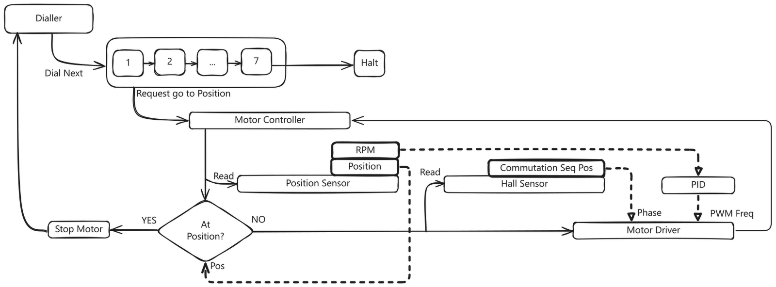
<p>Here is the control flow diagram for the basic dialler harness controlling the ESC.</p>

<p><img src="/assets/posts/Project-Update-2026/ESC_Flow_Diagram_Fixed.png" alt="" /></p>

<p>The dialler iterates through its address, where each symbol corresponds to a position, and asks the motor controller to seek to that position. Repeat seven times.</p>

<p>The motor controller reads two different sensors: the hall sensors, which are used to calculate the commutation sequence position, i.e. which phase needs powering to continue fluid motion (1 to 6); and the quadrature sensor, which measures the change in angular position and is used for the relative position and the RPM.</p>

<p>The RPM is passed into a PID calculation, which adjusts the PWM effort applied to the motor to hold the setpoint speed (a constant).</p>

<h3 id="commutation">Commutation</h3>

<p>Commutation is the sequencing of the coils to ensure the motor is always driven. My commutation driver consists of the hall sense circuit, i.e. 3 hall effect sensors 120 degrees out of phase with each other. There are six states, used to set the currently active winding depending on the direction.</p>

<p>During the early phase of the project I heavily referenced Electronoobs’ <a href="https://electronoobs.com/eng_circuitos_tut19.php">sensored ESC project</a> for the electronics, and <a href="https://lucidar.me/en/actuators/commutation-for-bldc-motors/">this commutation guide</a> for the code.</p>

<p>In my implementation I have two lookup tables for hall sensor state to windings, one table for each spin direction. These are as follows. (In my notation, Winding_AB means Winding_SinkSource, i.e. connect A to ground and B to VDD.)</p>

<div class="language-c++ highlighter-rouge"><div class="highlight"><pre class="highlight"><code><span class="c1">// Declare Valid Hall States.	</span>
<span class="n">Motor</span><span class="p">.</span><span class="n">BindClockwiseWinding</span><span class="p">(</span><span class="n">State_101</span><span class="p">,</span> <span class="n">Winding_BA</span><span class="p">);</span>
<span class="n">Motor</span><span class="p">.</span><span class="n">BindClockwiseWinding</span><span class="p">(</span><span class="n">State_100</span><span class="p">,</span> <span class="n">Winding_CA</span><span class="p">);</span>
<span class="n">Motor</span><span class="p">.</span><span class="n">BindClockwiseWinding</span><span class="p">(</span><span class="n">State_110</span><span class="p">,</span> <span class="n">Winding_CB</span><span class="p">);</span>
<span class="n">Motor</span><span class="p">.</span><span class="n">BindClockwiseWinding</span><span class="p">(</span><span class="n">State_010</span><span class="p">,</span> <span class="n">Winding_AB</span><span class="p">);</span>
<span class="n">Motor</span><span class="p">.</span><span class="n">BindClockwiseWinding</span><span class="p">(</span><span class="n">State_011</span><span class="p">,</span> <span class="n">Winding_AC</span><span class="p">);</span>
<span class="n">Motor</span><span class="p">.</span><span class="n">BindClockwiseWinding</span><span class="p">(</span><span class="n">State_001</span><span class="p">,</span> <span class="n">Winding_BC</span><span class="p">);</span>

<span class="c1">//Anti-Clockwise; Hall State &amp; Winding Response.</span>
<span class="n">Motor</span><span class="p">.</span><span class="n">BindAntiClockwiseWinding</span><span class="p">(</span><span class="n">State_101</span><span class="p">,</span> <span class="n">Winding_AB</span><span class="p">);</span>
<span class="n">Motor</span><span class="p">.</span><span class="n">BindAntiClockwiseWinding</span><span class="p">(</span><span class="n">State_100</span><span class="p">,</span> <span class="n">Winding_AC</span><span class="p">);</span>
<span class="n">Motor</span><span class="p">.</span><span class="n">BindAntiClockwiseWinding</span><span class="p">(</span><span class="n">State_110</span><span class="p">,</span> <span class="n">Winding_BC</span><span class="p">);</span>
<span class="n">Motor</span><span class="p">.</span><span class="n">BindAntiClockwiseWinding</span><span class="p">(</span><span class="n">State_010</span><span class="p">,</span> <span class="n">Winding_BA</span><span class="p">);</span>
<span class="n">Motor</span><span class="p">.</span><span class="n">BindAntiClockwiseWinding</span><span class="p">(</span><span class="n">State_011</span><span class="p">,</span> <span class="n">Winding_CA</span><span class="p">);</span>
<span class="n">Motor</span><span class="p">.</span><span class="n">BindAntiClockwiseWinding</span><span class="p">(</span><span class="n">State_001</span><span class="p">,</span> <span class="n">Winding_CB</span><span class="p">);</span>

</code></pre></div></div>

<p>When a state change is detected, the new active winding is cached, and drive is called: this shuts down all windings, then activates the new winding pair. A change to the PWM effort from the PID controller can also force the windings to be re-evaluated with the new PWM value.</p>

<p>A minor note on moving from the Nano to the Pico:</p>

<p>I needed to add a daughter board with an op-amp to get clean voltage thresholds. The previous circuit was just a voltage divider, giving roughly half the supply voltage as the low level. On the Nano this was below the high threshold, but on the v4 I was getting 1.6V for the no-magnet state, which is above the Pico’s rather low 1.3V high threshold. I fixed this in v4.3 by bringing the op-amp onto the board, eliminating this board.</p>

<h3 id="speed-control">Speed Control</h3>

<p>With a brushed DC motor, speed control is easy. More voltage is more current across the coils, which induces a stronger magnetic field, which means stronger attraction and thus faster rotation. Less voltage, the opposite.</p>

<p>With a brushless DC motor, less voltage probably just means your ESC MOSFETs don’t turn on, and the thing does precisely nothing. <strong>PWM</strong> (pulse width modulation) is the common way of tackling this in digital circuits: chopping the signal into periods of ON and OFF, and varying the ratio of on to off (the duty cycle) so that the average voltage is reduced.</p>

<p>I did try a constant PWM approach, but at any constant PWM value the motor has some degree of acceleration and eventually reaches full speed. I needed a dynamic system that could respond to the actual speed. Enter PID.</p>

<h4 id="pid">PID</h4>

<p>Proportional, Integral, Derivative (PID) is a common control algorithm for keeping a system at a setpoint. It works on active feedback, taking the deviation from the target on each cycle and weighting the three P, I, D factors to generate a new control input, the output PWM value in this case, with the goal of converging the error to 0.</p>

<ul>
  <li>Proportional - responds to the current error; the bigger the gap, the harder it pushes to close it..</li>
  <li>Integral - accumulates error over time, so it keeps pushing until any lingering gap (the steady-state error) is gone. Too much of it causes overshoot.</li>
  <li>Derivative - responds to how quickly the error is changing, braking the approach to reduce overshoot and oscillation (damping).</li>
</ul>

<p>I initially implemented my PID controller on the v2 before I took a break from the project in 2023. It never really worked reliably on that platform. On the v4, however, it mostly worked out of the box.</p>

<p>I do currently have issues with the D term, which has a habit of violent overreaction, especially when starting up or nearing the target. The D term is <code class="language-plaintext highlighter-rouge">delta error / delta time</code>, and as dt is minuscule, it tends to be disproportionately large given the output range is only 0-255.</p>

<p>I’m not completely sure how to solve this yet. A tiny D constant seems to help, as does increasing the sample time for measuring speed, e.g. it’s very unstable at 0.025 seconds, but fairly okay at 0.05 seconds. I’m sure there’s a balance to be struck, given how coarse the reading is at low speeds: even a single position sensor tick can make a large difference to the calculated speed. Earlier revisions used a rolling average, but that may just harm the responsiveness of the system. For now it’s good enough, but I need to revisit this.</p>

<h4 id="stupid">Stupid</h4>

<p>One notable ‘fun’ mistake I made a few years ago now was particularly painful when I finally realised. It may be the stupidest self-inflicted software performance bug I’ve ever caused, simply because it took the better part of a year to figure out. For context, compared to the original ESC, I completely rewrote the software, so this got lost in that. One of the things I added was a quick debug readout on a 20x4 LCD. Yeah, turns out I2C is very slow. Writing a letter to that thing takes 40μs. It would appear doing a full debug dump in the main loop every cycle wasn’t wise.</p>

<p>The failure mode was insidious: it would complete a few rotations before entering oscillating motion. It was leaving the phases active longer than it should. I only noticed this once I got an oscilloscope, where the signalling length inconsistency was as clear as day. Before that, I’d wrongly assumed it was a detection issue with the hall sense board, and must have redesigned that thing ten times in the process. Since I only really work on this project at weekends, this killed all the early momentum.</p>

<h2 id="position-control">Position Control</h2>

<p>The Stargate needs to be able to move any of the 39 glyphs to the top position. This problem splits into two parts: knowing the position of the ring, and being able to stop rotation at an exact position.</p>

<p>Overthinking this caused me one of the biggest headaches of the entire project. At the top of the original Motor One post there is this statement of intent.</p>

<blockquote>
  <p>The primary objective of Motor One is to construct a to-project-final-scale BLDC type motor which has the following functions, spin direction control, variable speed control to slow RPMs and precise positional control.</p>
</blockquote>

<p>I should have written this in bold across the wall of my workshop. I convinced myself the requirement here was for an <em>absolute encoder</em>. Mostly because I thought it would be cool for it to not need a homing sequence. This is bloody difficult to do, and I didn’t manage it. I then tried a few incremental encoder types before settling on a quadrature encoder, which works well.</p>

<h3 id="absolute-encoder-via-grays-code">Absolute Encoder via Gray’s Code</h3>

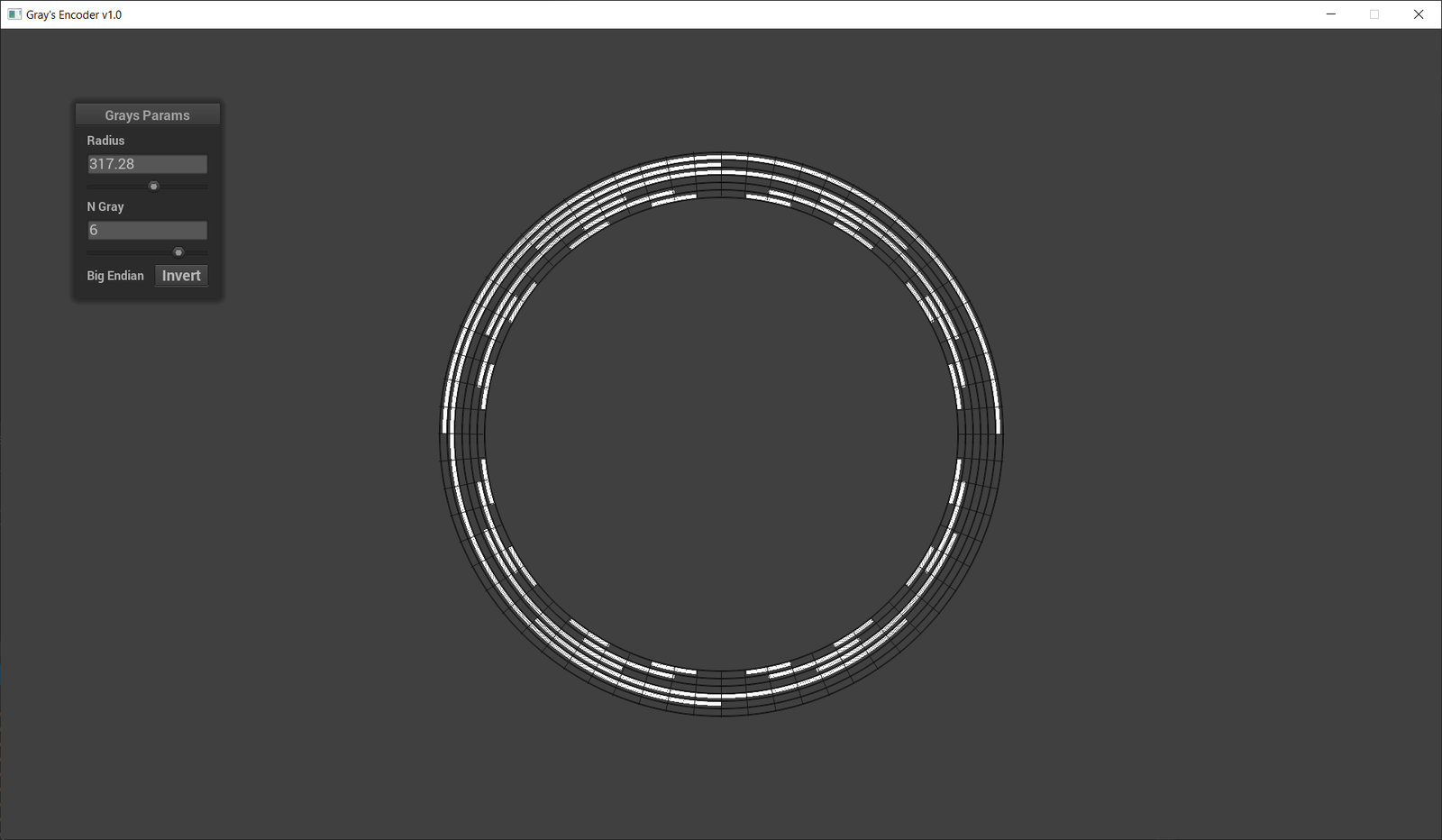
<p>An absolute encoder is an encoder which retains knowledge of its position without power. Gray code is one method of achieving this, where every step of the encoder’s resolution has a unique code, physically rendered onto a code ring as a reflected binary pattern. At any given instant it can read this code to know its position.</p>

<p>Gray code in particular also has innate error detection properties, as each code will be exactly 1 bit different from its neighbour, so if that isn’t the case you’d know you have a bad read. I made a program to generate these patterns, which ideally I’d have printed onto a disc for the sensor to read.</p>

<p><img src="/assets/posts/Project-Update-2026/GraysCode.png" alt="" /></p>

<p>I used an S9227-03 linear image CMOS sensor from Hamamatsu Photonics in an attempt to read the code, but couldn’t get it to read any of my test patterns. The only success was during a test where I backlit a 2.54mm pin header with a torch, getting the expected waveform on my oscilloscope. Turns out this sensor, which is clearly marketed for spectroscopy, needs the target to be self-illuminating.</p>

<p><img src="/assets/posts/Project-Update-2026/AbsoluteEncoder31.jpg" alt="" /></p>

<p>A possible solution suggested to me by an engineer from Hamamatsu was to have a phosphorescent target which emits in the wavelength range the sensor detects, but is excited by one it doesn’t. It did finally highlight the bigger problem, though: why exactly was I even trying to do it this way? It’s wholly unnecessary.</p>

<p>I had convinced myself it was a requirement. The primary advantage of this kind of encoder is you don’t need a homing sequence, which I thought would look a tad naff. The engineer pointed out I could probably just hide the initial homing as part of a first random rotation, or lock the rotor and store the last position in an EEPROM if absolutely necessary. Honestly the first random rotation would be fine.</p>

<p>I think there’s a lesson in target fixation in here somewhere. I at least had fun making the driver circuit, interpreting the sensor’s datasheet to write the driver code, and making my first practical SMD PCB. But this approach is a complete dead end. It also showed me the difference simply talking to someone makes when problem solving, rather than keeping everything in your own head.</p>

<h3 id="incremental-encoder---quadrature">Incremental Encoder - Quadrature</h3>

<p>An incremental encoder is a type of relative encoder. It tracks the difference in position from its initial position, but doesn’t have any actual understanding of where that initial position is in absolute terms. Once power is lost, wherever it happens to lie becomes the new zero position. To get an actual non-relative zero position you perform a homing sequence, which is to say you have some other sensor which only triggers when the rotor is at your true zero position.</p>

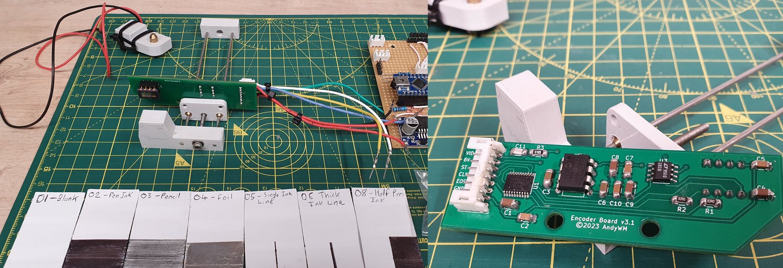
<p>I have tried a few sensors here, initially a few variations on an optical photo-interrupt sensor, like the one pictured below.</p>

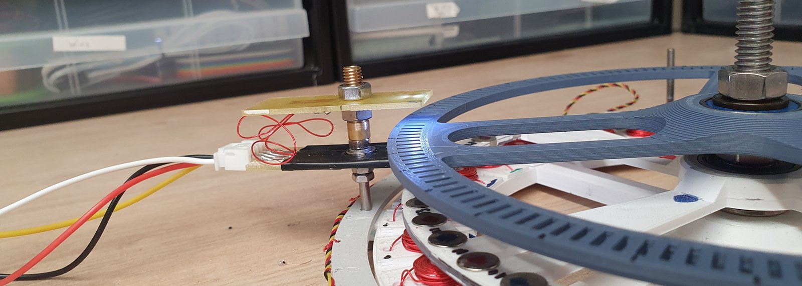
<p>Then finally the S4506, a neat little quadrature sensor, also from Hamamatsu. The quadrature package is simply the right choice here. Those optical endstops might be okay for coarse positioning, but they’re not really suitable for this problem otherwise. You also really need the ability to tell direction.</p>

<p><img src="/assets/posts/Project-Update-2026/OldSensor.png" alt="Photo-Interrupt Sensor" /></p>

<p><img src="/assets/posts/Project-Update-2026/InstalledQuadratureSensor.jpg" alt="S4506" /></p>

<p>While both use slotted discs, with an illumination source opposite a photo sensor, the photo sensors are quite different. The S4506 has 4 light sensitive zones, some onboard comparators, and outputs two logic signals which can be decoded and used to determine direction (<a href="https://www.hamamatsu.com/content/dam/hamamatsu-photonics/sites/documents/99_SALES_LIBRARY/ssd/s4506_kpic1004e.pdf">datasheet</a>).</p>

<p>I did initially have problems with the S4506. One was simply that my original 180-segment code ring was out of spec: the datasheet asks for a 1.56mm centre-to-centre slot pitch, which works out at about 162 slots.</p>

<p>The second problem was my software implementation for the signal processing. I tried just using interrupts, but ended up missing ticks. The Pico came to the rescue here, specifically PIO (programmable I/O): dedicated, simple I/O processors that can offload the handling of hardware protocols. I did have a go at writing my own. You write these in a very simplified assembly language with nine instructions, where you end up doing weird things like using JMP with its compare argument when you want arithmetic. Fortunately for me, while going over Raspberry Pi’s docs I found <a href="https://github.com/raspberrypi/pico-examples/blob/master/pio/quadrature_encoder/quadrature_encoder.pio">this example</a>.</p>

<p>It’s precisely what I needed, and it “just worked”. People are damn clever: this thing implements a state machine by calculating the program counter directly off the input. How do you even think of solutions like that?</p>

<h2 id="mechanical">Mechanical</h2>

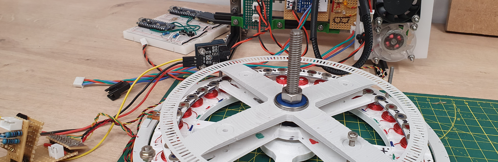
<p>Not a lot has actually changed here mechanically since the original. It has become readily apparent, as this project has dragged on, that plastic is an <strong><em>awful</em></strong> material to make a rotor out of; mine is now extremely distorted. It took me an embarrassing amount of time to realise how much internal stress those 40 alternating-polarity, 1kg-pull neodymium magnets pressed into the rotor would cause.</p>

<p>Future iteration should be be metal. Speaking of which, since the original prototype I have acquired a CNC machine, a mini lathe and a manual mill, which opens up more interesting options.</p>

<p>Bearings? I did write up a post on my bearing experiments in June 2022, I will have published that in conjunction with this post. The conclusion I came to was pre-machine tools: that I should try rollers, likely off-the-shelf flanged bearings, to seat the rotor into. That conclusion doesn’t stand, in reality I will need a custom thin-section bearing, I had PCBWay CNC me one out of stainless steel, after trying to make that myself in my workshop. Which I still get the odd metal splinter from years later… Let’s just say this still requires more R&amp;D.</p>

<h2 id="bldc-vs-stepper-motors---an-aside">BLDC vs Stepper Motors - An Aside</h2>

<p>This is a difficult question considering the time invested. Am I even building the right thing?</p>

<p>A stepper motor is a subclass of BLDC, and is the kind of motor generally used for precise control systems; e.g. robotics, 3D printers, etc. I did consider steppers when I first started, but out of ignorance thought them the more complicated option, so I built my axial-gap 3-phase BLDC, which in reality was the more complicated choice.</p>

<p>The main advantage of a stepper motor is that precision control is inherent to how they work. I wouldn’t need a closed-loop encoder to track position: provided the motor doesn’t stall, your position is the number of steps you have commanded the motor to move.</p>

<h4 id="electrical-differences">Electrical Differences</h4>

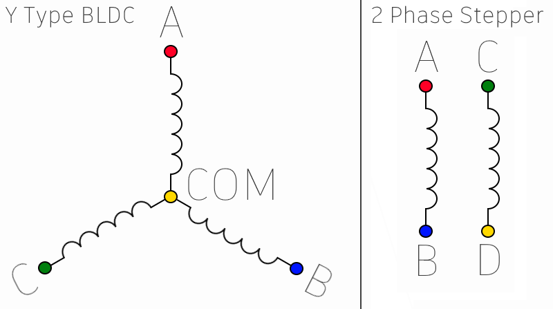
<p>The most common type of BLDC motor has three phases, i.e. three groups of electromagnets, connected in a Y configuration, i.e. sharing a common junction. Because of this common junction, two phases must be in use for the motor to do anything. Which two, and what they’re doing, is controlled in software on the ESC, which uses MOSFETs to connect one end to ground and the other to the supply voltage. The sequencing is relatively complex, and needs extra hardware, such as hall sensors or circuitry to detect back-EMF on the unused coil.</p>

<p>A hybrid bipolar stepper motor has 2 completely independent phases which can be used in conjunction with each other to give very precise control over a ‘step’. For example, they can be used in full-step mode, where only one phase is used, pulling the rotor over by 1 ‘slot’, or, more commonly, microstepping: a fractional step mode where they work together in a kind of tug of war to move it some fractional distance between slots.</p>

<p><img src="/assets/posts/Project-Update-2026/ElectricalComparisionBLDC-YvsStepper.png" alt="" /></p>

<p>An aside on stepper drivers. Until I worked on the encoder test rig recently, I’d never actually dealt with these directly. Turns out… they’re really simple to use, and pretty neat commodity ICs. As far as I can tell, provided I was within the current limits, if I went the stepper route I could practically replace the entire ESC with a single stepper IC, e.g. an A4988 or a more modern driver like a TMC2130. The IC has internal MOSFETs for both phases and presents a really simple interface to the microcontroller: enable, direction and step, plus a way to set the microstep mode. All the complex timing is handled on-chip.</p>

<p>The microstepping itself is pretty clever: the chip produces out-of-phase sine wave approximations on both phases, resulting in a smooth transition between slots.</p>

<h4 id="physical-differences">Physical Differences</h4>

<p>Superficially the two are similar. Electromagnet coils for slots on the stator, permanent magnet poles on the rotor. The difference is in the number of slots and poles. Motor One has 30 slots, meaning if you track one of the 40 magnets around a complete revolution, fully energising the coils in sequence, it will move into 30 stable positions: a coarse resolution of 12 degrees. A typical stepper used in a 3D printer has 200 or 400 slots, for a coarse resolution of 1.8 or 0.9 degrees. If you’ve ever tuned steps on a 3D printer, this is where the 200/400 steps per rev thing comes from.</p>

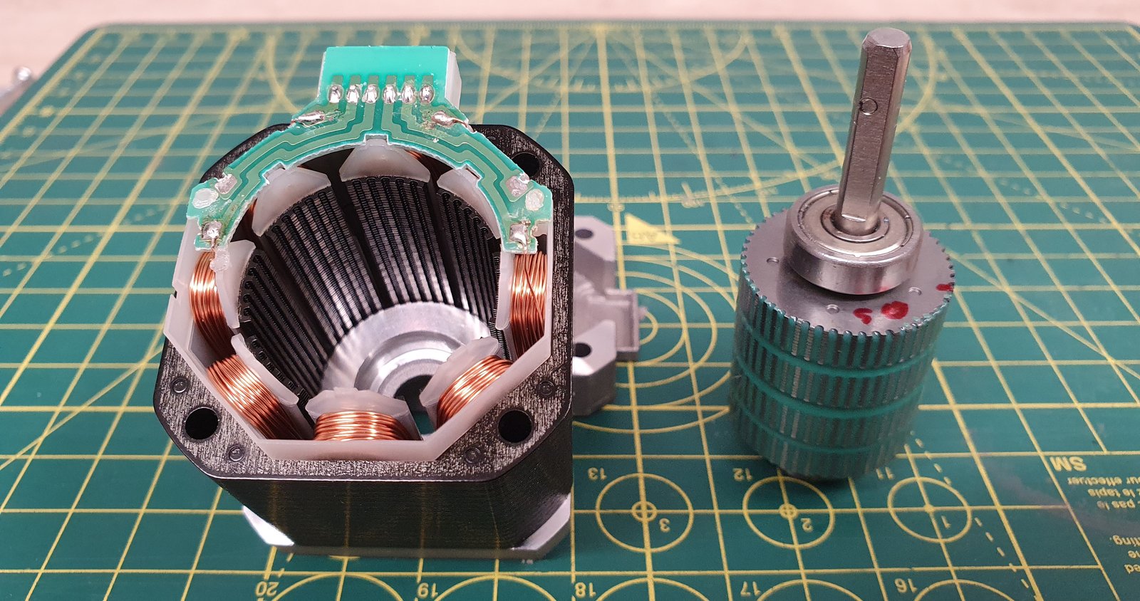
<p>The way they accomplish this is the noteworthy thing: you can’t just multiply the number of coils and magnets, as they’d be too absurdly small to even function. If you look inside one, they look like gears. They have multiple “teeth” per electrical coil, or magnet. Each prominence works as if it were its own mini magnet.</p>

<p>The other effect of increasing the pole count is to reduce your max speed, along with other characteristics like torque and acceleration. Though that reads like a list of things I’m trying to reduce anyway…</p>

<p><img src="/assets/posts/Project-Update-2026/Nema17StepperMotor.jpg" alt="" /></p>

<p>A note here for completeness’ sake, since it took me a minute to understand. The pictured motor is a 200 step motor. The actual term for these ‘gears’ is cups. At first glance it looks like this has 4 cups, but they’re actually in pairs as far as alignment goes, so it actually has 2 cups. If you count the teeth you get 50 per cup, 100 unique teeth positions. That seems like it should produce a 3.6 degree angle, not 1.8. That’s not how it works, though. The actual formula for the step angle is:</p>

<p><code class="language-plaintext highlighter-rouge">Step Angle = 360 / (Rotor Cup Teeth Count * Number of Phases * Number of Pole-Pairs)</code></p>

<ul>
  <li>Rotor cup teeth - how many teeth per cup: 50.</li>
  <li>Number of phases - how many electrical phases the motor has: 2.</li>
  <li>Number of pole pairs - how many poles on the stator have their teeth fully aligned with the teeth on the rotor when it steps: 2 for this motor.</li>
  <li>360 / (50 * 2 * 2) = 1.8. Or just 50 * 2 * 2 = 200 steps per rev.</li>
</ul>

<h4 id="comparing">Comparing</h4>

<p>Electronically, steppers are simpler, especially if you can just buy an IC that does all the hard bits for you.</p>

<p>Mechanically, however, they’re more complicated. Motor One already has a lot of slots for a BLDC, a natural consequence of it being an awkward, large-diameter, disc-shaped motor. I don’t think I can practically increase the number of magnets and coils by that much, as their strength drops to a quarter for every halving in size.</p>

<p>If I did want to make a stepper motor, I would have to make the intricate gear-like structure, which would have to be machined out of a ferromagnetic metal like steel. I could never have done that when I started this project, but I’ve taken up machining as a hobby since. It would likely be doable now. I would probably need to revisit the axial arrangement.</p>

<p>That said, there’s no reason a BLDC can’t do what I need it to. With the addition of a closed loop position sensor, it will work just as well. It’s just required a lot more development. A stepper motor was probably the correct choice for this application. I may be able to get some of the benefits by increasing the number of magnets and poles while keeping it a BLDC. I know I said this is problematic, but the motor can currently get up to about 400 RPM if you let it go full tilt. There may still be some performance I can sacrifice here…</p>

<h2 id="whats-left-whats-next">What’s Left, What’s Next?</h2>

<h3 id="motor-one">Motor One</h3>

<p>I’ve largely neglected this part of the project in the last couple of years. I have an in-progress refactor of the ESC code to flesh out the dialler into something more akin to what will actually be needed, stubbing out the functionality for the lights, chevron lock, and audio.</p>

<p>I’ve run this software on the latest ESC, in a spin test mode like back in 2021, and it does work.</p>

<p>The last key element of Motor One from the original plan was a milestone for developing a custom rotor bearing. I tested one on Motor One, and it did spin up. I don’t think that version of the bearing is what I’ll proceed with, but that it worked at all is encouraging.</p>

<p>The v4.3 board has a regression: it omits some important pull-downs for the MOSFET driver. Dead short. I’ve bodged this on the board I built, and I don’t have enough new features to justify ordering a new revision just yet. This board is likely what I’ll continue with for the next motor.</p>

<p>But I think Motor One itself, as a research platform, is EOL.</p>

<h3 id="motor-two">Motor Two?</h3>

<p>I’ve already started designing Motor Two. Initially I wanted it to follow the Stargate’s size constraints more closely than Motor One, and when I tried, I immediately rediscovered some of those constraints: 4mm (0.23kg pull) magnets. I think I should stick with them, but I’d like this platform to be engineered in a way that actually lets me tinker.</p>

<p>As far as the ESC goes. The speed control algorithm currently uses random PID values, and it’s not quite as stable as I’d like. I want to refine this. Possibly with automated tuning, e.g. the Ziegler–Nichols method?  The position itself may benefit from its own PID controller, or at least something to account for inertia. Alternatively, since first writing this post I’ve learned about something called field-oriented control (FOC). It needs more sensing in the electronics and is a more complex control algorithm, but in a world with AI now, it’s probably worth looking at. It’s how precision devices such as servo drives are typically run.</p>

<p>If Motor One was the “Fundamentals Pathfinder”, Motor Two will be the “Refinement Prototype”: taking the lessons and general design of the first and building a better one.</p>

<p>Main Goals:</p>

<ol>
  <li>Assembly thickness. The pathfinder is an inch thick; the target is 1cm or less.</li>
  <li>Custom Bearing. The rotor assembly must have an appropriate integrated bearing.</li>
  <li>Easily Adjustable Coils. This likely runs at odds with the assembly thickness, but the coils are a major part of the thickness, and this will likely take many iterations to get right. These can’t be soldered to the bus bars like in Motor One.</li>
  <li>Easily swappable rotor assembly. This is already the case with Motor One, but I’m stating it as a goal for Motor Two as the custom bearing may cause some complications.</li>
</ol>

<p>As a likely consequence of these, I expect Motor Two to be an all-metal construction.</p>

<p>Secondary goals:</p>

<ol>
  <li>Electronics miniaturisation.</li>
  <li>Tune performance characteristics. It may be possible to get more favourable low speed performance with a different coil/magnet count. If we make things easily swappable, it may be a good opportunity to experiment.</li>
</ol>

<h3 id="motor-three">Motor Three???</h3>

<p>‘Proof of Concept’, this is a little way off. This will be taking whatever comes out of Motor Two, and making it fit into the form factor of a Stargate. There’s a possibility this ends up just becoming the gate prototype.</p>]]></content><author><name></name></author><category term="Stargate-Project" /><summary type="html"><![CDATA[It’s November 2026!? The last post was in 2021. This blog was meant as a journaling effort… That’s gone well. This project hasn’t exactly progressed as quickly as I would’ve hoped. Nevertheless, progress has been made!]]></summary></entry><entry><title type="html">Motor One - Finding a Bearing</title><link href="https://www.andywm.com/stargate-project/2022/09/25/Motor-One-Finding-a-Bearing.html" rel="alternate" type="text/html" title="Motor One - Finding a Bearing" /><published>2022-09-25T12:00:00+00:00</published><updated>2022-09-25T12:00:00+00:00</updated><id>https://www.andywm.com/stargate-project/2022/09/25/Motor-One-Finding-a-Bearing</id><content type="html" xml:base="https://www.andywm.com/stargate-project/2022/09/25/Motor-One-Finding-a-Bearing.html"><![CDATA[<h2 id="a-note-from-2026">A Note from 2026</h2>

<p>I’m publishing this post for posterity. It was originally written in the summer of 2022. The conclusion I reached at the end isn’t what I’ll be using: I tried it, and it didn’t work. It still stands as part of the research effort, though. See the revised conclusion at the end for where things went next.</p>

<p><em>The original post continues…</em></p>

<p>When I initially designed Motor One, I didn’t want to worry about the bearing until I had the key elements in place: fine control of the rotor’s position and its speed. That wasn’t necessarily wrong, but the initial design had something of a timebomb in it. I’ll detail that in a moment; first, the constraints.</p>

<h3 id="the-driving-constraints">The Driving Constraints</h3>

<p>While there are no hard constraints on the Motor One pathfinder, the requirements of the future motor still cast something of a shadow. It has to be possible to iterate this design into something which fits inside a model Stargate.</p>

<p>The gate’s symbol ring, which the rotor will be part of, is a tapering surface at the thin diameter of the gate. It also accounts for about half the width between the inner and outer diameters of the gate. At these sizes, it’s easier to scale up than it is down. Two natural constraints fall out of this:</p>

<ul>
  <li>Minimise the thickness of the rotor. (target=2mm)</li>
  <li>Minimise the width of the rotor. (target=1cm)</li>
</ul>

<p>Another set of constraints comes from physics: permanent magnets are stronger than electromagnets of the same size (like those used in the stator). The strength of a permanent magnet is a function of the inherent magnetism of the material, and the volume of the magnet. So for the same material, if we halve the volume, we get a quarter of the strength. So, given we still need to optimise the stator to minimise the coil size in the future, it follows that:</p>

<ul>
  <li>We optimise the permanent magnet last, keeping it as strong (therefore as large) as we can, for as long as we can. (target=8mm dia)</li>
</ul>

<h2 id="a-problem-of-consistency">A Problem of Consistency</h2>

<p>The problem I’ve been experiencing while developing the motor’s speed controller, which got worse as I slowed the motor down, was inconsistency. By which I mean the RPM varied as it spun, and the motor would often end up in a stalled state.</p>

<p>I can’t say how many index rings (the hall sensor rings) I’ve made in trying to combat this problem. Then I noticed it: the distance between the rotor and the sensor ring was varying <em>quite</em> drastically as it spun, by as much as a centimetre. While I don’t yet know if this is the entire problem, it certainly can’t be helping.</p>

<p>Either way, <em>it’s not meant to do that…</em> It seems prudent to fix the mechanical system before trying to write a precision control system on top of it.</p>

<h2 id="rotor-mk1---skateboard-bearings">Rotor Mk1 - Skateboard Bearings</h2>

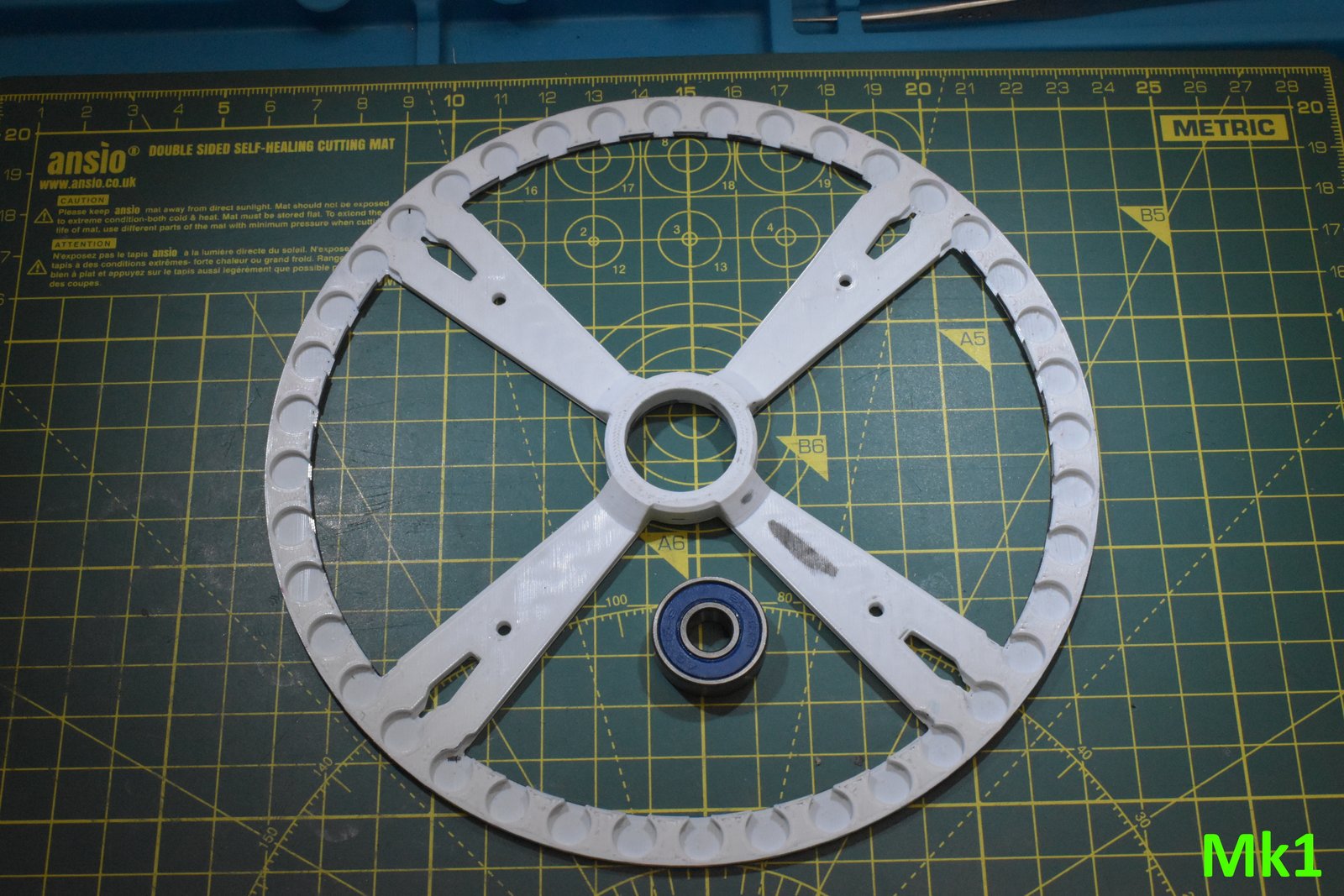
<p>The original design, used for all the development so far, has an off-the-shelf 608 skateboard bearing in the centre, with spokes leading away to support the rotor/ring holding the 40 permanent magnets. The construction is 3D printed out of PLA.</p>

<p><img src="/assets/posts/Motor-One-Finding-a-Bearing/Mk1.jpg" alt="" /></p>

<p>The issue, the timebomb, is that PLA creeps under load, i.e. it deforms over time if a constant force is applied. Turns out <em>40 N42 neodymium magnets with 1.1kg of pull, held millimetres apart in opposite polarity, is quite the load</em>. The original rotor has substantially deformed. The process of replacing this began my iteration nightmare.</p>

<p>As it turns out, at this thickness with a bunch of holes for the magnets, it seems like I got lucky that this design worked at all. All the subsequent polymer rotors I’ve made, in PLA, PC and PETG (I even CNC milled one out of POM), have imploded once I inserted even half the magnets.</p>

<p>I’m not really sure why this original worked for as long as it did. If I had to speculate, this was one of the last parts I made with my old 3D printer, Bodgebot. I’ve transitioned from Cura to PrusaSlicer, and the new printer meant new profiles, so I just took the default ones as a basis. It’s possible the number of perimeters and top/bottom layers was higher, or maybe I used an infill that did a better job of stiffening the surfaces. It’s worth investigating. There may be a polymer design that does hold up… but that’s not the direction I went in.</p>

<h2 id="rotor-mk2---like-rotor-mk1-but-metal">Rotor Mk2 - Like Rotor Mk1 but Metal</h2>

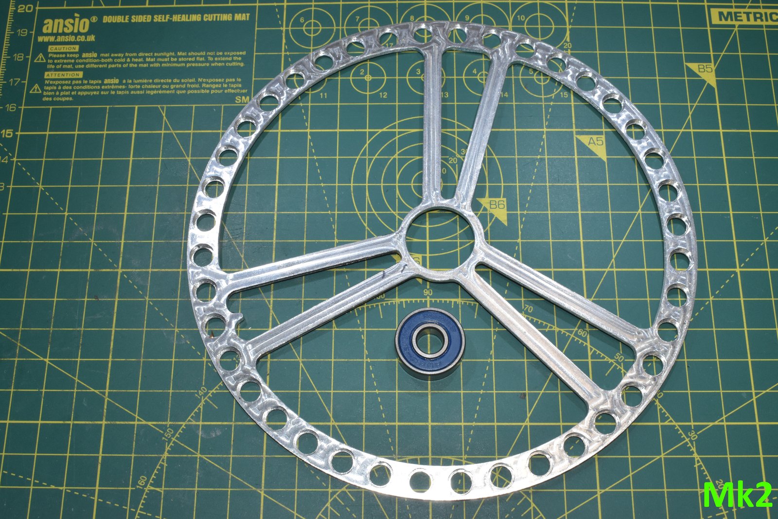
<p>I bought a fancy new toy recently, a Nomad3 Desktop CNC by Carbide 3D. I can machine aluminium with this. So that’s what I did: I optimised the Mk1 design for CNC. To my surprise, this didn’t work. The separation from the index ring was still variable, perhaps <em>worse</em> than before. It turned out the bearing was inserted slightly off-axis, and since the ring is ~8cm from the centre, any angular offset here produces quite a deflection.</p>

<p>It’s also possible the press fit caused the aluminium part to deform. I’m still getting used to CNC; the bore was undersized, and it took a lot of force to insert.</p>

<p><img src="/assets/posts/Motor-One-Finding-a-Bearing/Mk2.jpg" alt="" /></p>

<p>At this point, across Mk1 and Mk2, I’d spent a fair amount of time and effort fixing a part I need to replace anyway. That’s the final issue with this type of rotor: <em>The Stargate does not have spokes</em>. If fixing this design, which was meant to let me focus on the ESC control, is taking this much time, I should probably spend it making something closer to the system I’ll end up using anyway.</p>

<h2 id="rotors-mk3--mk4---ball-bearings">Rotors Mk3 &amp; Mk4 - Ball Bearings</h2>

<p>The obvious solution is to scale up what I’ve been using so far, a 608 bearing. Let’s look at one.</p>

<p><img src="/assets/posts/Motor-One-Finding-a-Bearing/608_macro.png" alt="" /></p>

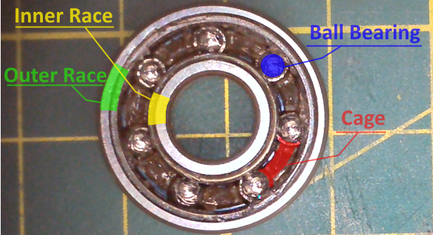
<p>Picture courtesy of a low-resolution USB microscope. I’ve annotated the four primary components.</p>

<ul>
  <li>Outer Race - larger ring structure with a groove for ball bearings on the inner surface.</li>
  <li>Inner Race - smaller ring structure with a groove for ball bearings on the outer surface.</li>
  <li>Ball Bearings - when torque is applied to the outer or inner races, these roll between them, allowing free rotation.</li>
  <li>Cage - contacts only the ball bearings, not the races, and keeps them a fixed distance apart, preventing them from bunching up.</li>
</ul>

<p>The races are the interface of rotation, one side will usually be fixed relative to some other structure, while the other can rotate freely. In this bearing, the only thing holding it together is the interference fit of the ball bearings. If the ball bearings disappeared, it would fall apart.</p>

<h3 id="stator-expansion-interface">Stator Expansion Interface</h3>

<p>A common element in all the following iterations is that they use the <em>Stator Expansion Interface</em> (SEI), meant for the index ring, rather than the centre mount bolt. The interface is four equally spaced M3 holes, starting 45 degrees off-axis, at a radius of 94.456mm. <em>There may have been some arbitrary CAD involved here…</em></p>

<p>The fact I need to use this interface means I don’t really care about the size of the static race, as long as it’s not obviously impossible to scale down, it can be as large as it needs to be to mate simply with the SEI.</p>

<h3 id="rotor-mk3">Rotor Mk3</h3>

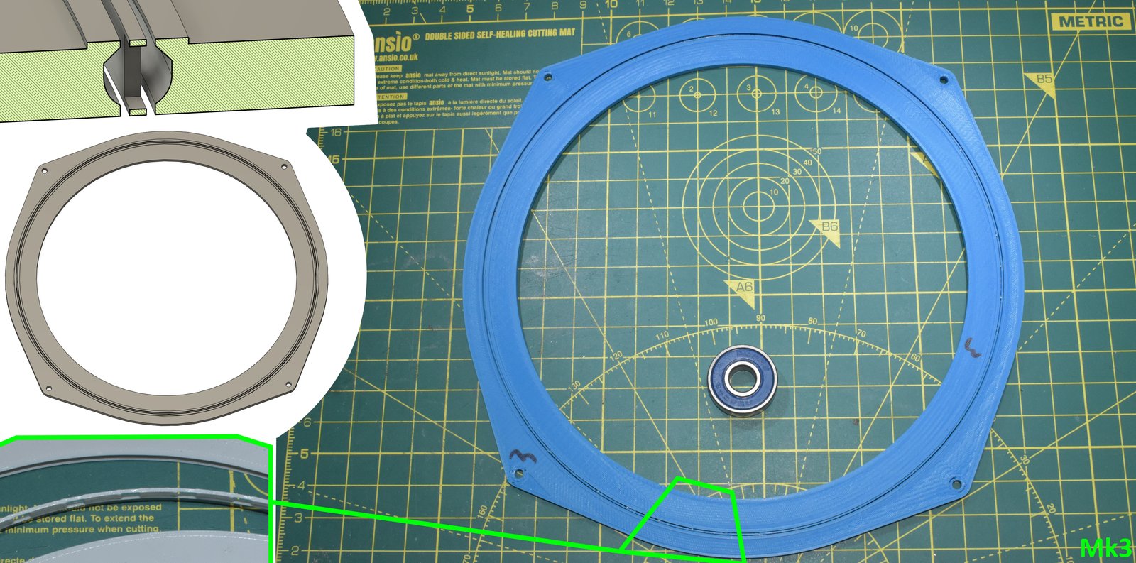
<p>Mk3 implements all the elements of the 608 bearing: the static outer race, the inner race integrated into the rotor, a cage, and fifty 2mm steel ball bearings. The entire assembly is just over 2mm tall.</p>

<p><img src="/assets/posts/Motor-One-Finding-a-Bearing/Mk3.jpg" alt="" /></p>

<p>In the top left of the image above there’s a cross section of the CAD assembly. During printing, there’s a pause at the top of the straight before the 45-degree overhangs. At this point the ball bearings are inserted and the print resumed, capturing them in place. In the bottom left there’s an exploded arrangement of the 3D print showing this same area, highlighted in green, which better illustrates the anatomy of the cage.</p>

<p>This design omits the magnet slots; that was merely to speed up printing while iterating. It took several iterations to tune the tolerances for smooth rotation. It does rotate smoothly, but it has a fatal flaw, or three.</p>

<ul>
  <li>If you place any axial force on the rotor, or flex the assembly, the entire thing just detonates. Motor One is an axial-gap motor. All the force is axial.</li>
  <li>The cage is fragile at only 0.5mm in width.</li>
  <li>The cage is very flexible and has a habit of contacting the inner or outer race as it travels, adding friction.</li>
</ul>

<p>The key issue here is that I can’t practically use bigger ball bearings: 2mm is already at my height limit, and that’s still too small to make this design work. That comes down to plastic being flexible. In this design the bottom and tops of the races are only a few layers thick, and the overlap between the race and ball-bearings on either side is only 0.5mm.  If the assembly flexes by even half a millimetre it breaks apart. This is perhaps made worse by the shape of the race’s groove. Ideally its cross-section would be a semicircle; it’s not. This is a compromise to make it 3D printable.</p>

<p>The cage brings its own issues, for this design to work it has to be printed in place. To give it the best chance of having any strength, I used a 0.25mm nozzle; printing 2 perimeters, with staggered seams. This was to minimise the seam being a weak-spot. At 0.5mm, the clearance on either side is pretty tight at 0.275mm, so I don’t think it would have been practical to make this any thicker. Even then, there’s still a weak spot, the top and bottom bridges between the ball-bearing slots are only a single layer. It’s very prone to breaking here.</p>

<p>The cage also had a habit of slipping off centre slightly, still capturing the ball-bearings, but shifting enough to catch on one of the races, potentially dragging.</p>

<p>An additional, noteworthy but minor, issue is noise. The 50 ball bearings rattle as it turns. This suggests poor manufacturing tolerances, but even fractionally tighter and the system bound up. Grease may have helped here, but I’d probably have to have applied it with a needle.</p>

<p>Despite these flaws, the Mk3 was the best performer until the Mk7.</p>

<h3 id="rotor-mk4">Rotor Mk4</h3>

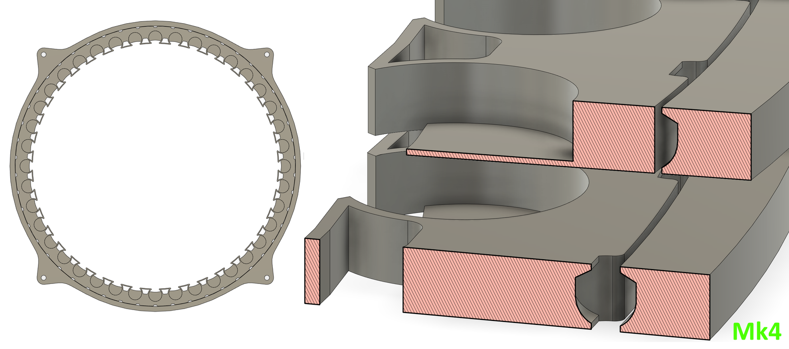
<p>Mk4 is an evolutionary branch of the Mk3; asking the question, “can I get rid of the cage”?</p>

<p>As discussed above, the main flaw with the Mk3 is it’ll send ball-bearings into low-earth-orbit given half a chance. If we dispose of the cage, we regain about 0.75mm of space, which we can use to further enclose the ball-bearings.</p>

<p>The design and implementation is similar to the Mk3, there are cavities into which the ball bearings are inserted during a mid-print pause, after which the print resumes, entombing them.</p>

<p>On the right side of the image below, there are stacked cross-sections of the same area. The open area on the outer static-race is like that on the Mk3; a constant profile around the circumference. On the inner rotor-race however this area tapers to meet the centre-line. Once a ball-bearing is inserted here, it’s walled and can’t traverse sideways.</p>

<p><img src="/assets/posts/Motor-One-Finding-a-Bearing/Mk4.png" alt="" /></p>

<p>This does keep the ball-bearings at a fixed distance from each other… but in the process introduces severe binding.</p>

<p>I know cageless bearings exist. But none of the designs lock the travel of the ball-bearings to one of the races, and many use alternating direction roller-bearings over ball-bearings. That would appear to be for a very good reason. The cage doesn’t just keep the ball-bearings apart. It critically allows them to move as an independent system at their natural speed.</p>

<p>This is simple physics: for a rotating body, the further out from the centre you measure the faster the apparent speed to cover the same angle about that centre. The ball bearings are not points with zero width; their centre of travel is further out than the rotor race’s outer diameter, which only imparts enough tangential force to move them as if they were. So naturally, if we constrain them to the rotor, we’re going to be dragging them for them to keep up.</p>

<p>This is a terrible bearing. Not only does it not rotate smoothly, it comes apart more easily than its predecessor: it’s bogging steel into plastic, which pushes back with a spring force, causing the assembly to self-destruct.</p>

<h2 id="rotors-mk5--mk6---bushing">Rotors Mk5 &amp; Mk6 - Bushing</h2>

<p>A bushing is the simplest kind of bearing. It’s two surfaces which rub against each other. They’re generally preferred for low-speed high-torque applications.  My application is low-speed low-torque, so even better?</p>

<p>I know this works for a model Stargate, every animated gate I’ve seen has used this principle. The one I made in secondary school used this principle. This should have been at the top of my list of things to try. My main grievance with bushings is that the crunchy sound of plastic rubbing against plastic just bothers me.</p>

<p>I reasoned that I could leverage CNC here to make smoother parts from fancier materials than 3D printing allows, hoping to come up with a design which produced a more tolerable sound in operation.</p>

<p>I would say this section is included for completeness. Neither Mk5 nor Mk6 produced anything usable. Both were beset with machining problems due to my inexperience, though at a minimum they taught me some lessons.</p>

<h3 id="rotor-mk5">Rotor Mk5</h3>

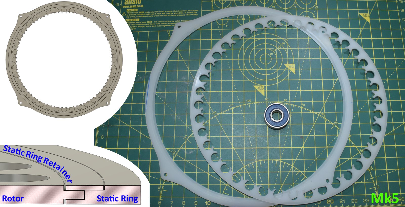
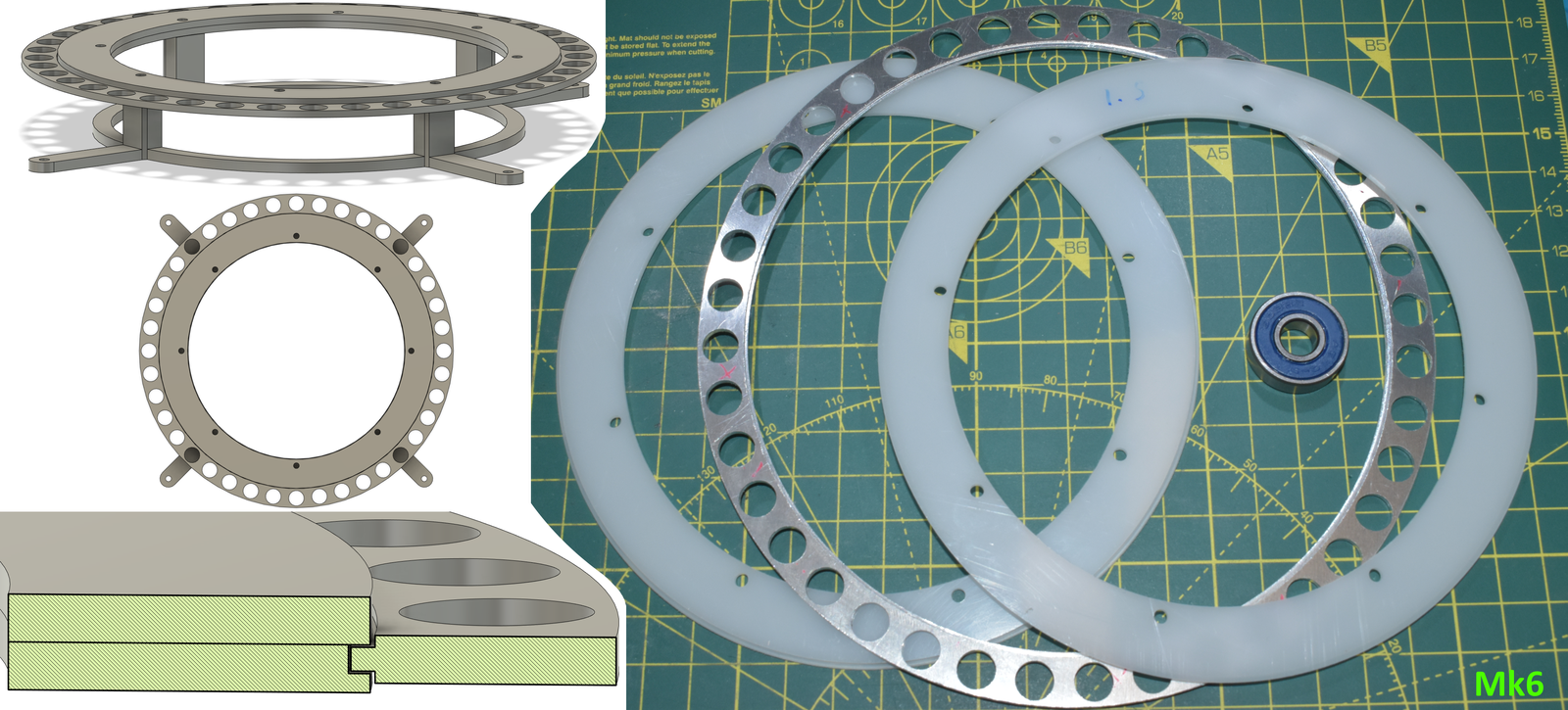
<p>Enter Mk5. It’s machined entirely from acetal (POM, aka Delrin), and has three parts; the rotor, the static ring, and the static retaining ring. The lower left of the image below is a cross sectional view.</p>

<p><img src="/assets/posts/Motor-One-Finding-a-Bearing/Mk5.jpg" alt="" /></p>

<p>Once the rotor is inserted, the static-ring-retainer is glued to the static ring, and the rotor is free to turn inside. At this point you may be noticing a discrepancy between the CAD on the left, and the object on the right.</p>

<p>The bottom of the magnet slot was bored straight through. Other problems: the fit between the rotor and static ways is too tight. The ‘stick out’ on the outer diameter of the rotor is meant to have equal spacing above and below, and be 1mm thick; it turned out 0.75mm thick, i.e. one cut is much deeper than the other. It’s out of spec. Precision machining is hard and requires skill and experience I don’t yet possess; it’s all new to me, and I’m still learning.</p>

<p>I didn’t have enough POM left for another attempt, so that same day I ended up designing the Mk6 instead. The Mk5 still had a lesson to offer, though.</p>

<p>I mentioned in the Mk1 section how I got lucky; this was where I realised it. A design feature of the Mk5 carried forward from the Mk4, is the branch like structure at the edge of the open magnet slots: a compliant mechanism for inserting the magnets. The mechanism works, the magnets are easy to insert, up to a point.</p>

<p>The insertion order for the magnets is all-even polarity, followed by all odd. With all evens inserted, once about a quarter of the way through the odds, the rotor buckled into a cone shape. The earlier 3D printed versions had simply failed catastrophically; this, for the first time, demonstrated quite visually the interaction between these very strong magnets. Which is obvious in hindsight.</p>

<h3 id="rotor-mk6">Rotor Mk6</h3>

<p>Mk6’s design fell out of a realisation I had when I ran out of material for the Mk5: if the static element was on the inside, I’d have used less material…</p>

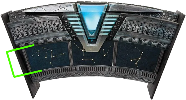
<p>On the Stargate, there is a small section under the ring. Below is a reference image of the Atlantis gate from the Propworx auction. The green bracket highlights the ring area. (This gate was actually a repurposed SG-1 ‘hero gate’, i.e. one of those used for on-location filming around Vancouver, so all the proportions are the same.)</p>

<p><img src="/assets/posts/Motor-One-Finding-a-Bearing/sgaref.png" alt="" /></p>

<p>At my scale, this area under the ring would be thin, but a bushing might fit. To use this kind of bearing on Motor One, I needed to create an adaptor for the SEI, which is the strange circular tower in the image below.</p>

<p><img src="/assets/posts/Motor-One-Finding-a-Bearing/Mk6.png" alt="" /></p>

<p>In the bottom left there is the usual cross sectional view. The design is similar to Mk5, with three components, static ring (bottom), static-ring-retainer (top) and the rotor (right).</p>

<p>The static elements are both 2mm thick, made of POM and this time bolt together. I did this for simplicity’s sake. Had I iterated on this design, I’d likely have changed the square ‘stick out’ into a V shape, with the corresponding groove split across two 1mm plates. Either way, these two parts did turn out in-spec.</p>

<p>The rotor however did not.</p>

<p>The rotor is made of aluminium, is 2mm thick, and has ways machined on both sides of the inner circumference, While the depth is right this time, one of them wasn’t concentric, so it didn’t seat correctly in the static element. The part was scrap.</p>

<h3 id="a-cnc-aside">A CNC Aside</h3>

<p>Double-sided parts present a difficult problem: when you flip the part you introduce positional and rotational error. One way to mitigate this is ‘indexing’: alignment holes that repeatably fix the part in exactly the same location on your work platform. Alternatively, you build a jig that aligns the part in much the same way.</p>

<p>In my case, I machined my stock to a known square size, then bored indexing holes mirroring the ones in the work platform. I used the Nomad’s ‘BitZero V2’ corner finding block. I suspect my process for squaring it was naive and introduced the error, perhaps there was a slight burr. Either way, the way on the second side was off-centre by as much as half its intended width.</p>

<p>I need to practise machining, and double-sided machining in particular. The entire work flow is quite different from what I’m used to with 3D printing. I know my printers well enough to know what tolerances I need to bake into my designs, and which design patterns allow for which geometry.</p>

<h2 id="rotor-mk7---rollers">Rotor Mk7 - Rollers</h2>

<p>Did I replicate the right thing when I built the Mk3? I was attempting to scale up a 608 skateboard bearing. Perhaps that was misguided. While looking at bearing listings, I came across Lazy Susan type bearings. These are large radius bearings, quite similar in proportion to what I’m attempting. They come in all the same variety you’d expect from bearings, including ball-bearings. But many designs use rollers or wheels.</p>

<p>I had considered rollers previously. The original CAD for the Mk3 was designed to accept rollers instead, but I couldn’t find any that small, and there wasn’t a chance I was hacksawing 50 precision 2mm rods. But what if I don’t need 50?</p>

<p>Thus the Mk7 was born. There’s an elephant in the room with this design; I’ll get to that at the end.</p>

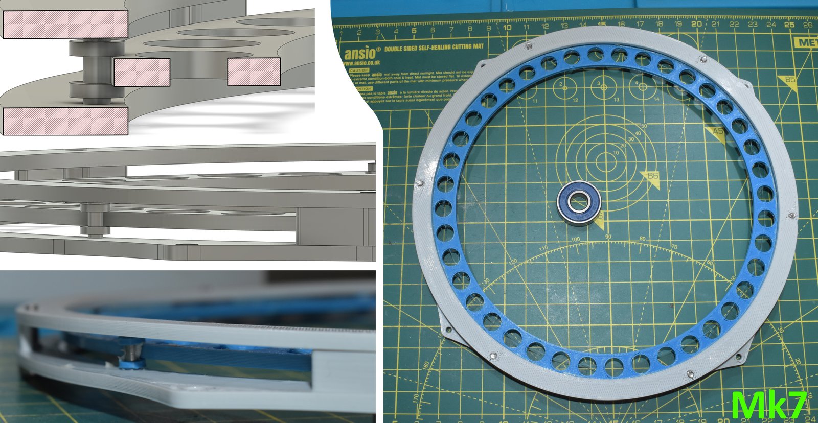
<p><img src="/assets/posts/Motor-One-Finding-a-Bearing/Mk7.jpg" alt="" /></p>

<p>Instead of 50 rollers, this design uses six, equally spaced around the circumference. Each is a 7mm steel rod, with 3D printed washers superglued to them 1mm either side of centre. The rotor is captive to these washers. The assembly is awkward, but not too difficult. The rotor is placed roughly in position, then each roller is inserted around it, and finally the retaining plate is bolted in above it, securing everything in place.</p>

<p>It turns smoothly in both standing and lying-flat orientations. The few contact points make little noise, and it doesn’t explode when loaded axially.</p>

<p>The ultimate proof will be when I replace the 3D printed stand-in with a milled aluminium rotor and try it live. But all indications so far are positive; this seems like a solid candidate design to iterate from.</p>

<p>About that elephant. Mk7 is almost a centimetre tall. That’s far beyond what I consider acceptable, so I’ll need to look into a miniaturisation scheme. But if push comes to shove, you can actually buy tiny flanged bearings; such as the F681, 1mm tall, 3mm OD, 1mm ID. They’re expensive, at £8 a bearing at the time of writing, but definitely an option.</p>

<p>At this point, I’m thinking my miniaturisation strategy would be to bring the rotor height down to 1mm at the outer circumference, and to get access to a lathe to machine a better flanged roller, as the current one is mostly limited by how small and repeatable I can make a part with hand tools. In my head I don’t see why it needs to be any larger than 3mm. It does take more space out of the area I wanted to conserve for electronics, but it at least doesn’t take it around the entire circumference, only at 6 points.</p>

<h2 id="conclusion">Conclusion</h2>

<p>I believe the Mk7 is the best fit for Motor One. I intend to evolve the roller design to be more compact in Motor Two; if I can’t, I’ll re-evaluate my options, which would likely have to be some kind of bushing at that point.</p>

<p>Whatever happens, I think the rotor needs to be metal so it doesn’t deform long term under the internal loading of the magnets.</p>

<p>To summarise:</p>

<ul>
  <li>Off-the-shelf bearings in the style of Mk1 and Mk2 are out; the gate doesn’t have spokes.</li>
  <li>Captive ball bearings at my target thickness are too fragile, especially with plastic races. Metal races might work, but the machining needed to have a groove on the side is beyond what any tool I own could do.</li>
  <li>Bushings need further investigation. My implementation of them was too poor to pass fair judgement.</li>
  <li>Rollers or wheels seem well suited for this task.</li>
</ul>

<p>A humbling takeaway is that CNC is hard and I need a lot of practice. The CAD skills I have are somewhat transferable, but even then designing for subtractive manufacture is different. CAM is considerably more complicated than a 3D printer’s slicer. And dealing with the real-world realities of stock sizes, tolerances and alignment is just something that’s going to require practice.</p>

<h2 id="revised-conclusion-2026">Revised Conclusion (2026)</h2>

<p>When I tried running the Mk7, it kept sticking. That may just have been down to the low precision of my rollers, and higher-quality ones might have worked. However, while drawing up the master CAD for Motor Two’s constraints, I realised there simply isn’t space for this kind of arrangement. In reality I have far less room than I thought, especially if I want to fit electronics and the chevron actuators in there too.</p>

<p>I had a stainless steel bearing race set machined through PCBWay’s CNC service, and that bearing ran on the motor. I’d still like to make one myself; since writing this post I’ve acquired a lathe and got a little better at CNC.</p>

<p>Here’s the result:</p>

<p><a href="https://www.youtube.com/watch?v=DldsclZsMhU">https://www.youtube.com/watch?v=DldsclZsMhU</a></p>

<div class="video"><iframe width="560" height="315" src="https://www.youtube-nocookie.com/embed/DldsclZsMhU" title="YouTube video" frameborder="0" allowfullscreen=""></iframe></div>]]></content><author><name></name></author><category term="Stargate-Project" /><summary type="html"><![CDATA[A Note from 2026]]></summary></entry><entry><title type="html">Motor One</title><link href="https://www.andywm.com/stargate-project/2021/06/25/Motor-One.html" rel="alternate" type="text/html" title="Motor One" /><published>2021-06-25T00:00:00+00:00</published><updated>2021-06-25T00:00:00+00:00</updated><id>https://www.andywm.com/stargate-project/2021/06/25/Motor-One</id><content type="html" xml:base="https://www.andywm.com/stargate-project/2021/06/25/Motor-One.html"><![CDATA[<p>Motor One is the first of three pathfinder projects. It’s purpose is to gain the requisite skills and knowledge to design and construct the motion system for the gate’s ring.</p>

<p><img src="/images/Coils.jpg" alt="Coils" /></p>

<p><em>The primary objective of Motor One is to construct a to-project-final-scale BLDC type motor which has the following functions, spin direction control, variable speed control to slow RPMs and precise positional control.</em></p>

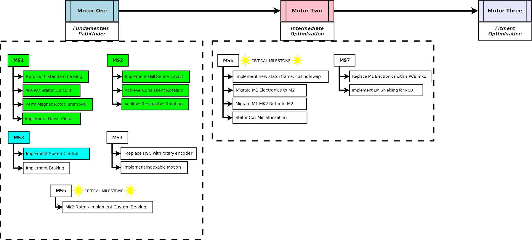
<p>To do this, I have something of a roadmap. There’s no point of planning out too far ahead, but I have a pretty good idea of what I want Motor Two to be, and what I need Motor One to accomplish to get there.</p>

<p><img src="/images/Roadmap.png" alt="" /></p>

<h3 id="milestone-zero">Milestone Zero</h3>

<p>Before I did any motor work, I did some preliminary tests with different electromagnet configurations, I never fully concluded these tests as a test accident was actually encouraging enough to just move onto the motor.</p>

<iframe width="480" height="360" src="https://www.youtube.com/embed/H9-bkGItSGg" frameborder="0"> </iframe>

<p>The parameters of the test do bear explaining though, as I still use this notation; wire diameter, coil radius, coil height. I selected two wire diameters 0.55mm (Type A), 0.75mm (Type B) and the notation I used for these coils was [A/B]H[height]W[width]. The version I selected for the motor was the largest in the test, the AH6W7 coil. 6 tall, 7 wide.  42 coils.</p>

<h3 id="milestone-one">Milestone One</h3>

<p>So… I set to building a motor. Motor fundamentals are out of scope here, though I may do another post detailing them in future.</p>

<p>The two primary components of a motor are the <strong>stator</strong> and <strong>rotor</strong>. For my design, the stator is the section with the electromagnets; which are in a non-overlapping,  3-phase configuration, in a 3:4 ratio with the permanent magnets in the rotor.  (Fantastic technical reference on those ratios here;  https://things-in-motion.blogspot.com/2019/01/selecting-best-pole-and-slot.html).</p>

<p>For development sake, the mark 1 rotor in this design uses an off-the-shelf 608 bearing as its centre bearing, though I know I will have to build a custom bearing for later milestones in Motor One. <em>The entire project actually hinges on the viability of that element. The gate can’t have a bearing in this position.</em></p>

<p>The stator has 30 electromagnet <strong>coils</strong>, implemented as <strong>Coil Plates</strong>. They are the above AH6W7 coil design. The plate itself is friction mounted in place. Then each end of each coil was routed through the stator to the underside via two holes at either side of the plate, where they were soldered appropriately.</p>

<p>I am using a typical BLDC Y- configuration. i.e. every coil in a phase is connected in series to every coil in its phase (every 3rd coil is connected together). Then at one end of this chain they are commoned together with the other 2 phases (to form a Y like joint), and the remaining side acts as the input to the phase. That way if you run current through a phase, and sink one of the other inputs to ground you get opposite polarity magnetic fields generated in the 2 now active phases, with the 3rd floating.</p>

<p>For Motor One, the coil design and coil plates won’t change. But I’d like to optimise this design in Motor Two, and would like a more easily swappable plate design.</p>

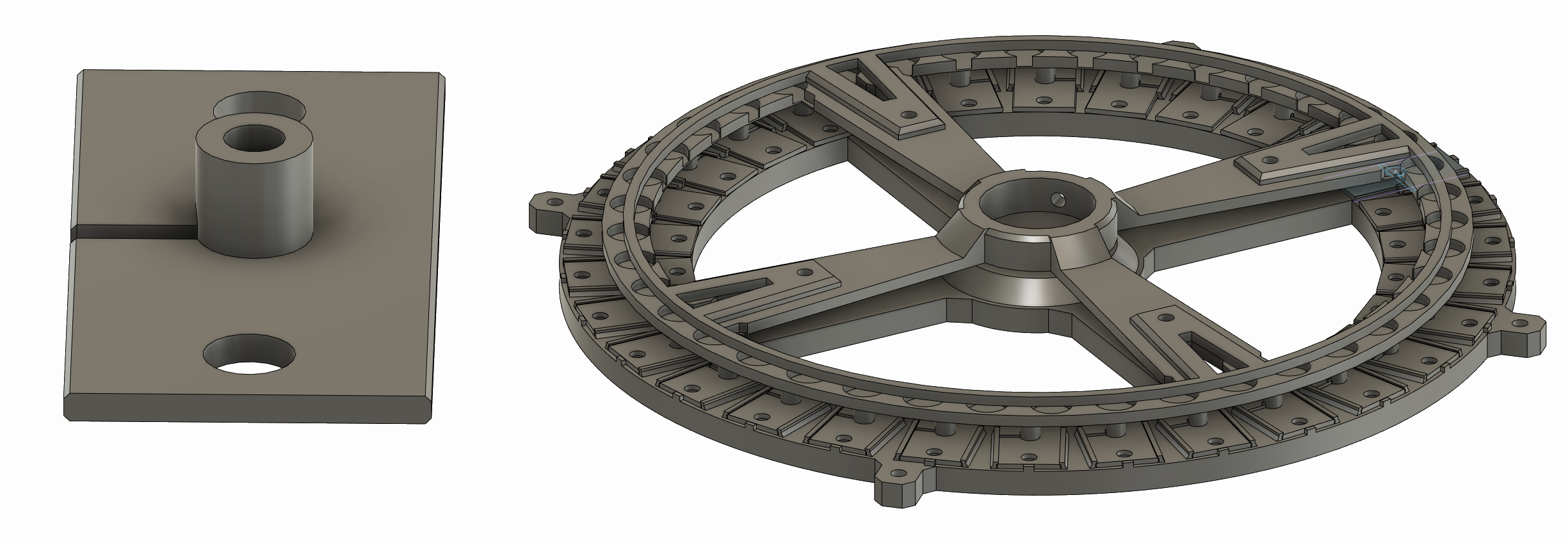
<p>Below are 3D renders of a coil plate without it’s coil on the left. And the whole of Motor One (without actual coils or the 608 on the right).</p>

<p><img src="/images/CAD_2.png" alt="CAD_2" /></p>

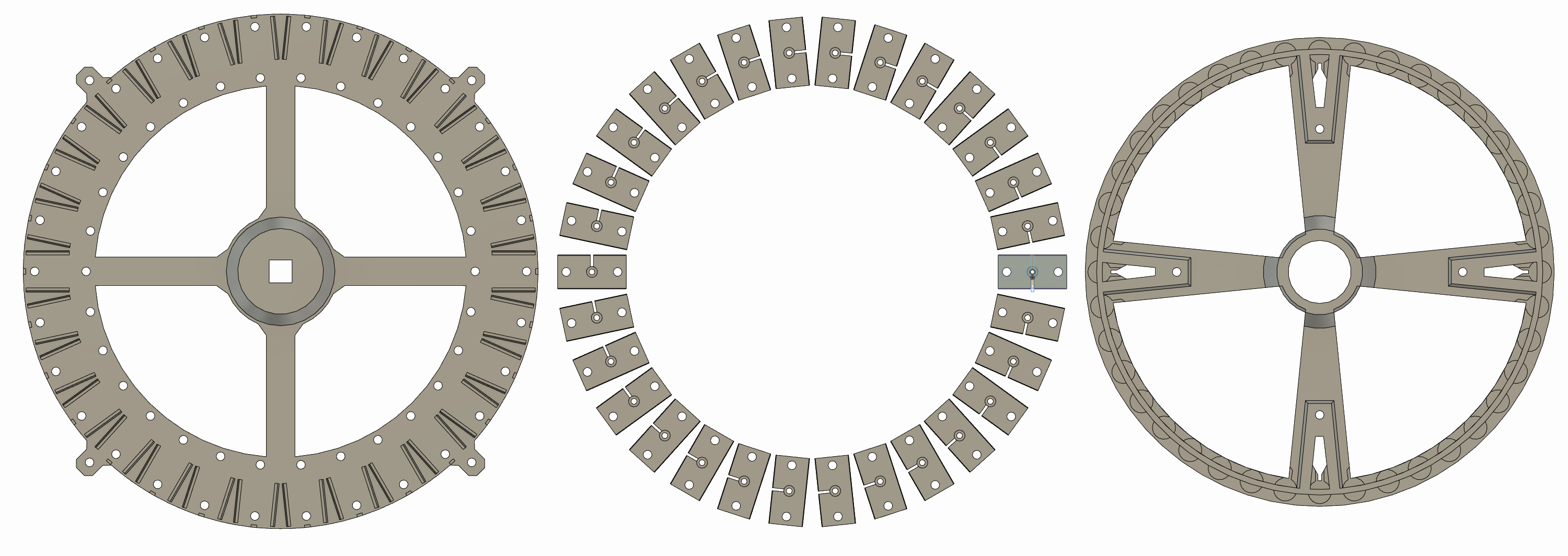
<p>Top Down; Stator Base, Coil Plates, Rotor</p>

<p><img src="/images/CAD_1.png" alt="CAD_1" /></p>

<p>The stator base has 4 expansion holes on it’s outer circumference, the rotor is actually split into two pieces. The main body, and a top retaining plate. I will probably remove the retaining plate in later designs.</p>

<p><strong>Basic Electronics</strong></p>

<p>I tried an off-the-shelf sensored ESC, but couldn’t get it to work, so I quickly set to building my own; which I would have to had done eventually anyway. I based my initial design off this project https://simple-circuit.com/pic16f887-sensorless-brushless-motor-control/ - this isn’t a sensored ESC, it uses Back EMF, but the I only needed the MOSFT arrangement, as at the time I only had N-Channel MOSFETs, this was the only design I could find which doesn’t use P-Channel’s for the high side. I also substituted the MOSFET drivers with BJT transistors, as I also didn’t have any of those.</p>

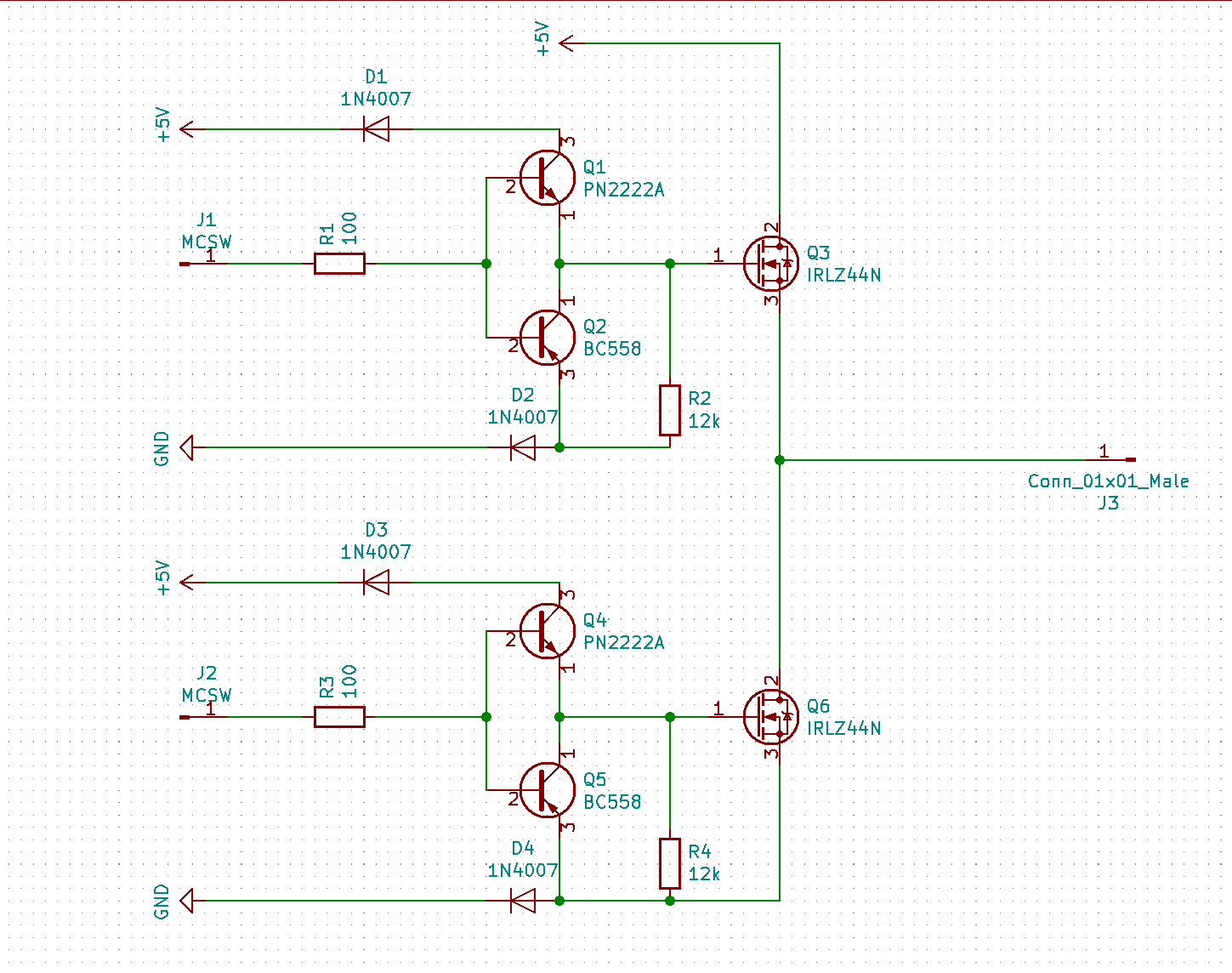
<p>I built 3 of these below, and also added different colour indicator LEDs in parallel with the input and the BJT transistor bases. (e.g. J1 to the connection between Q1 and Q2). Each has two inputs, J1 and J2, which go to the brain of my ESC, a venerable Arduino Nano. 5V applied to J1 makes the output at J3 high, 5V to J2 makes J3 grounded.</p>

<p><img src="/images/ElectronicsV1.png" alt="ElectronicsV1" /></p>

<p>Initially I tested without the sensor board, just to see if it would do.. something. Or better yet, to see if I could luck into rotation; and it did kind of work, I did get some kind of rotation maybe 1 in every 5 times. More often than not it just jumped erratically. Initial software - https://github.com/andywm/GateESC/commit/926ff934a161bfabe9f11f8ca7b9dbd7f39e03ea/src/main.cpp</p>

<iframe width="480" height="360" src="https://www.youtube.com/embed/8SSRhHoZOp8" frameborder="0"> </iframe>

<h3 id="milestone-two">Milestone Two</h3>

<p>So, I had achieved erratic motion, time to get fluid motion.</p>

<p>BLDC motors need some kind of feedback to know their position to correctly sequence the motor. A process called commutation, there are two common ways to do this;</p>

<p><strong>BEMF</strong> which uses induction in the floating coil, when the induced voltage crosses zero, you sequence the commutation. This looks difficult, so isn’t the route I went for…</p>

<p><strong>Hall Effect Sensors</strong>, magnet sensors basically. Placed 120 degrees out of phase with each other in between coils on the stator. They detect the magnets in the rotor when they pass over. 1 or 2 can be active at once, so produce 6 unique combinations indicating when the parament magnet is aligning with stator electromagnets. At which point you switch to the next phase in the sequence misaligning them again, continuing the process of the permanent magnets chasing the rotating field from the stator.</p>

<p>As a quick reference for the commutation table for a 3-phase motor I used this; https://lucidar.me/en/actuators/commutation-for-bldc-motors/</p>

<p>In my current version I built this apparatus and attached it to the stator using the expansion holes. Each sensor lies directly between two coils. Mine are not 120 degrees out of phase, they’re actually between consecutive coils. I think this works for me because I have 30 coils and 40 permanent magnet, so 120 degrees out of phase would be 10 coils distance. So the 10th coil will be the same as the 1st, as will the relative relation with the rotor magnets due to the 3:4 ratio. Which is convenient for me, as it means my apparatus can be ‘compact’.</p>

<p><img src="/images/IndexRing.png" alt="IndexRing" /></p>

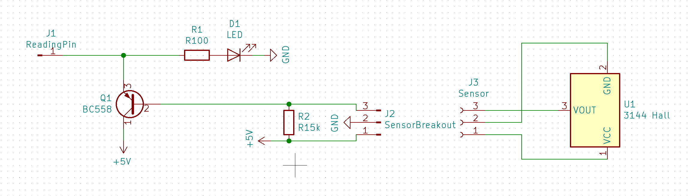
<p>The hall sensors I have are the linear (analogue ) type, rather than digital, so I had to make a bit of circuity to turn the voltage into a binary signal for the Arduino. For my 3144 hall, the stronger the magnetic field, the more Vout drops. So I put a pullup resistor from 5V to the Arduino input/Vout to get a nice high signal when it’s off. Then fed it into a PNP BJT transistor to; (A) give me a nice digital threshold for the signal. (B) invert the signal as active low for this bothers me irrationally. Really I could have done it with a NPN and just read LOW to mean on in software. But I digress.</p>

<p>The hall sense circuit is 3 of these next to each other. It has a nice indicator LED for when the sensor is detecting a magnet for debugging reasons.</p>

<p><img src="/images/HallCircuit.png" alt="HallCircuit" /></p>

<p>I reworked the control software for the ESC, it’s basically a re-write as the first version was just to get it to do.. something. This is the version I will build on. It implements the commutation sequences as well as directional control. And it works reasonably well. https://github.com/andywm/GateESC/blob/3cf6672638acaa5940a3b7476896cb69f5546901/src/main.cpp</p>

<iframe width="480" height="360" src="https://www.youtube.com/embed/RmfzqN9nT0U" frameborder="0"> </iframe>

<p>Although all-and-all though, this is actually just a stop-gap prove out aspects of the motor; to serve as a development platform. I will need the final ring to have full positional indexing, so will need something much more accurate than these hall sensors. The entire thing will essentially need to be an absolute rotary encoder. Knowing its position to high accuracy at all times. So, when I develop <em>that</em>. Well, I may as well use that for the commutation sequencing too.</p>]]></content><author><name></name></author><category term="Stargate-Project" /><summary type="html"><![CDATA[Motor One is the first of three pathfinder projects. It’s purpose is to gain the requisite skills and knowledge to design and construct the motion system for the gate’s ring.]]></summary></entry><entry><title type="html">Stargate Project - My History</title><link href="https://www.andywm.com/stargate-project/2021/03/06/Stargate-Project-My-History.html" rel="alternate" type="text/html" title="Stargate Project - My History" /><published>2021-03-06T01:30:00+00:00</published><updated>2021-03-06T01:30:00+00:00</updated><id>https://www.andywm.com/stargate-project/2021/03/06/Stargate-Project-My-History</id><content type="html" xml:base="https://www.andywm.com/stargate-project/2021/03/06/Stargate-Project-My-History.html"><![CDATA[<h1 id="stargate-project---my-history">Stargate Project - My History</h1>

<p>I’ve wanted to make an animated Stargate model for years now. I know there are designs on thingiverse; some are quite decent looking, but designing your own stuff is fun, it’s not like I have an awful lot else to do with my free time right now.</p>

<p>This project isn’t a new idea to me, I’ve actually been at it for years, granted at a dead stop. I’d like to change that.</p>

<h2 id="2010---kind-of-successful">2010 - kind of successful?</h2>

<p>I actually have made a terrible Stargate before, back when I was in secondary school as my year 10 DT project. It was 3 laser cut sheet layers of black acrylic that when laid together formed a track for the ring, which had gear teeth around it. The base had a cut-out for another gear on a DC motor to drive this. Inside the track there was conductive tape tracks for the LEDs, which were red as that was the only thing I could get my hands on at the time. I actually remember only having 6 available inputs, so it started the dialling sequence from chevron 2, with 1 always lit. You triggered the sequence by pressing a button on the front, the ring span dumbly, but alternatingly as lights lit up. I don’t have any pictures of it, and I’m kind of sad I didn’t pay to take it home after being graded.</p>

<h2 id="2017---new-project">2017 - new project.</h2>

<p>I joined Leigh Hackspace in 2017, and wanted a project to work on. After mulling for a bit, I realised it was obvious. A stargate. I figured a nice new environment to be productive in, it’ll be swell. It wasn’t. I aimed well beyond what I could reasonably have accomplished.</p>

<p>I’ll discuss the biggest snag remaining, I wanted ands still want an internalised drive for the gate, turns out tiny motors aren’t powerful, and sound like someone torturing a cat.</p>

<p>Here’s one of the later iterations of my previous design in trying to use an internal motor. This version did actually spin the ring without the cover plate, but the motor would quickly burn out, and would usually melt the mount; it’s a tiny brushed dc motor driving a worm gear mechanism.</p>

<p><img src="/images/Retrospective/WormDrive.JPG" alt="" /></p>

<p>I had given up hope, but I realised the potential for something quite cool. Could I build my own motor? This one failed too. Did make some interesting noises though.  Though, spoiler, I’m going to continue investigating this approach.</p>

<p><img src="/images/Retrospective/EMGate.JPG" alt="" /></p>

<p>And here’s the prototype graveyard.</p>

<p><img src="/images/Retrospective/Box.jpg" alt="" /></p>

<h2 id="2019---this-blog-a-restart-attempt">2019 - this blog, a restart attempt</h2>

<p>I started a blog at the end of 2019 in the hopes that it would give me an opportunity to write about my previous failures and analyse, share and learn from them. Turns out all that does is really demotivate you if you’ve still not got anything to show. So detailed mentions of that project end on this page. Since it kind of went no where.</p>

<h2 id="2021---this-blog-again-restart-2">2021 - this blog, again, restart #2</h2>

<p>I’m starting this blog over,  I’d like to use it to document what I’m going to do, rather than what I fucked up historically. I still want the internalised drive as my USP, and still think the EM drive offers the best path forward, just not how I did it in the past.</p>

<p>Let’s see where this leads.</p>]]></content><author><name></name></author><category term="Stargate-Project" /><summary type="html"><![CDATA[Stargate Project - My History]]></summary></entry></feed>